

Reliable structures, very precise drawings
CYPECAD was brought about to carry out the analysis and design of reinforced concrete and steel structures, subject to horizontal and vertical forces, for houses, buildings and civil work projects.
Its use guarantees maximum analysis reliability and the best drawing design, including the following elements:
- Floor slabs
- Beams
- Supports
- Stairs
- Foundations
- General data
- Data entry (Structure geometry)
- Integrated 3D structures (Connection between CYPECAD and CYPE 3D)
- Analysis
- Design load analysis
- Seismic analysis
- Capacity design criteria for seismic design of concrete columns and beams
- Capacity design criteria for seismic design of concrete floor slabs
- Seismic analysis with force amplification in open floors or with partitions that are less rigid than on other floors
- Interaction of the structure with the construction elements
- Correction due to base shear for seismic design using dynamic analysis method
- Fundamental period of the structure with user values
- Seismic spectrum specified by users
- Fire resistance check
- Welded and bolted joints
- Analysis using multiprocessors
- Export to TEKLA® Structures and in CIS/2
- Export to IFC format
- Results
- Drawings
- Reports
- Properties that distinguish CYPECAD
- CYPECAD versions and modules
Joist floor slabs can be composed of concrete (generic), precast reinforcement, precast prestressed, in situ, steel (T and double T sections), truss joists and timber. The deflection is calculated in all cases.
Additionally, it allows for flat and solid slabs, waffle slabs, hollow core slabs, and composite slabs (steel deck) to be used.
The floor beams may be reinforced concrete, steel (normal or castellated), mixed and timber. Corbels can also be introduced.
More information can be found on the Concrete beams webpage.
The program allows for reinforced concrete columns, steel columns and composite steel and concrete columns.
Shear walls can be rectangular or adopt on plan any shape made up of rectangles.
Walls may or may not have lateral pressures and may be reinforced concrete, generic load bearing or concrete block walls with or without reinforcement (the dimensions of the blocks are introduced by the user or from manufacturer catalogues such as NORMABLOC National Association of Concrete Blocks and Masonry Manufacturers).
 Walls may contain openings. The program calculates the necessary additional reinforcement of the openings in the reinforced concrete walls (lintel, guardrail, lateral and diagonal) and the lintel reinforcement when The gaps are introduced in concrete block walls. Additionally, it is possible to obtain a report of the checks that are carried out in the analysis on this reinforcement and can be viewed on screen or printed out.
The crown beam is also designed for all types of walls as is the intermediate beam at floor level in the case of generic load bearing walls and concrete block walls.
More information can be found on the webpages:
 CYPECAD analyses and designs stair slab reinforcements as isolated elements of the structure. Depending on the geometry, type and support arrangement and the applied gravitational loads, the program establishes the reactions on the main structure, which are applied as line and surface loads (in the case of steps built on the slab) in their corresponding permanent and live loadcases.
The program calculates the stairs by finite elements, taking into account the usual two loadcases for the stair analysis: permanent loading and live loading.
CYPECAD displays on screen the reinforcement of each of the spans making up the stairwell. It is also possible to consult, in a three dimensional view, the displacements, forces and see the deformed shape of each span.
The foundation can be fixed (by pad foundations or pile caps) or ‘floating’ (with slabs on grade and foundation beams, having to define the subgrade modulus upon applying the Winkler theory).
The foundations may also be designed by having only introduced column starts.
Isolated or combined pad foundations may be composed of reinforced concrete or mass concrete and may support multiple columns.
Pile caps can hold a multiple number of piles. A wide range of options are available:


 Rectangular pile caps for one, two, four and five piles
-
 Triangular pile caps for three piles
 -
 Strip pile caps for three to thirty piles
  Rectangular pile caps for multiple piles (grid distribution from three to thirty piles per side)
 Pentagonal pile caps for five to six piles
 Hexagonal pile caps for six to seven piles
Both the pad foundations and pile caps allow for several columns and shear walls to be placed on them without restraining their position on the foundation element.
The strap beams also act on the pile caps and the tie beams brace the elements.
Base plate design is carried out for any steel column arrangement simple sections and composite sections).
More information on the foundations designed by CYPECAD and CYPE 3D can be found in the Foundation analysis and design section.
 Wind and earthquake (spectral mode analysis) loads are selected, by selecting the properties as described in the codes. In both cases second order effects (P-delta) may be taken into account.
There is no limit as to how many loadcases, line, surface or point loads can be applied and at which position.
The program automatically generates any loadcase combination defined by the user in accordance with the conditions that have been indicated (compatible, incompatible or simultaneous). For example, the loadcase combination of a load composed of a generic live load and a the action of a truck load at various positions is generated automatically. The positions of the truck are incompatible amongst one another but compatible with the generic live load and the remaining loadcases of a different nature.
Users can also define their own project situations to personalise the combinations that are going to be used in the corresponding analysis of the structural elements of the job.
This has been adapted for national and international codes.
CYPECAD has numerous analysis options, with explanations and on screen graphs, to personalise the analysis, design and reinforcement by means of tables.
Data entry (Structure geometry)
The geometrical introduction of a job in CYPECAD is carried out on plan views on each of the different levels of the structure, the same way as drawings are visualised out on site and so avoiding three dimensional data introduction which is much more complex.
With CYPECAD the data of the structure can be introduced in three different ways:
 When introducing a structure you may use any of the three methods mentioned above.
- Automatic job introduction: DXF, DWG and CAD/BIM models.
The module: Automatic job introduction: DXF, DWG and CAD/BIM models of CYPECAD has two options available which have been conceived to automatically generate the structure using the information from the following types of files: - Import of IFC files generated by CAD/BIM programs
Using the Automatic introduction IFC option, the Automatic job introduction: DXF, DWG and CAD/BIM models allows for the import to CYPECAD of IFC files generated by the main CAD/BIM programs (Allplan, Archicad, Revit Architecture). By means of an assistant, the user confirms and completes the information obtained from the IFC file, after which, the following elements of the structure are generated: - Floor distributions
- Dead and live loads on floors
- Columns
- External perimeter and internal openings perimeter beams
- Partition and façade wall line loads
- Drawing templates of each floor
- By means of DXF or DWG files
Using the Automatic introduction DXF/DWG option of the Automatic job introduction: DXF, DWG and CAD/BIM models module, the user completes a series a data by means of an assistant, which then allows the program to interpret DXF and DWG files to automatically generate the structure of the job: - Floor distribution
- Dead and live loads on floors
- Columns
- External perimeter and internal openings perimeter beams
- With the help of DXF or DWG drawings used as templates.
The supports and beams of the structure can be introduced with the aid of a drawing in DXF or DWG format. It is possible to capture the elements of the DXF or DWG drawing so they remain adjusted at the positions held in these drawings with maximum precision. - Introduction using global or relative coordinates.
The program also allows for columns and beams to be introduced using coordinates with respect to an origin or any other point.
More information on importing IFC files in CYPECAD can be found in Automatic job introduction: DXF, DWG and CAD/BIM models.
 CYPECAD also allows for the job to be exported to IFC format. To do so, the user license does not necessarily have to include the "Automatic job introduction: DXF, DWG and CAD/BIM models" module. More information can be found in the Export to IFC format section in the CYPECAD page.
More information on importing IFC files in CYPECAD can be found in Automatic job introduction: DXF, DWG and CAD/BIM models
 When introducing a structure you may use any of the three methods mentioned above.
Any of the three methods may be combined during the introduction of a structure:
- Automatic job introduction (importing IFC files or interpreting DXF and DWG files)
- With the help of DXF and DWG files used as templates
- By means of global or relative coordinates.

The beam manager allows for the beams that are going to be introduced to be straight or curved, and their introduction mode can be continuous or discontinuous. DXF or DWG displacements and adjustments are possible during beam entry or once they are situated on plan. You may also add as many floors, columns, beams or panels as you wish.
If you have acquired the automatic job introduction module, not only will you be able to adjust beams to DXF or DWG lines, but also to open or closed polygons in these drawing files.
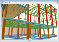
It obtains the 3D view, solid and immediate (with conical or isometric perspective) of any floor or of the entire building, without the need of having to previously analyse the job.
It is possible to move around freely inside the structure when it is visualised with conical perspective. In the 3D view, the floors and walls possess a degree of transparency making it easier to visualise those elements that remain hidden.
Both horizontal or inclined slabs may be introduced. Inclined slabs are simple to introduce as only the inclined plane has to be defined. This can be done by defining 3 level points, by a given slope line or by the maximum slope line. This slope is then assigned to panels that have been previously introduced horizontally and hence avoiding a complex 3D introduction.
It is possible to copy all the geometry of a floor from one floor to another, as can the properties of a panel (including the insertion point) to another panel on the same or different floor.
Integrated 3D structures (Connection between CYPECAD and CYPE 3D)
CYPECAD and CYPE 3D are connected by means of the Integrated 3D structures, which allow for a structure to be included in CYPECAD with the same design assumptions as it would have in CYPE 3D.
 |
 |
 |
 |
An integrated 3D structure is a steel, aluminium or timber structure, made up of nodes and bars with six degrees of freedom which is connected and bonded to the main building structure managed by CYPECAD.
The integrated 3D structures of CYPECAD is not technically a module: to be able to define the integrated structures, the user has to have the license to use both CYPECAD and CYPE 3D. Several integrated 3D structures can be added to a single CYPECAD project.
An integrated 3D structure is connected to the CYPECAD structure by means of connection points which may be situated on the following CYPECAD elements: columns, column starts (where a pad footing or pile cap can be defined later on), beams, flat slabs, waffle slabs, mat foundations or foundation beams.CYPECAD allows for an Integrated 3D structure to be introduced in two different ways:
- By directly creating a CYPE 3D job within CYPECAD.
- By importing a CYPE 3D job into an existing or new CYPECAD job.
CYPECAD and CYPE 3D have common modules (Pad footings, Pile caps, Baseplates, Fire resistance check, Parallel analysis with two processors and Parallel analysis with up to eight processors). With the Integrated 3D structures, CYPECAD also benefits from the exclusive CYPE 3D modules (Aluminium sections, Timber sections, Joints I Welded – Warehouses with rolled and welded steel I sections, Joints II Bolted - Warehouses with rolled and welded steel I sections, Expot to TEKLA and Export in CIS/2 format for Graitec Advance Steel). The use of these modules requires for the user to have the corresponding license permits.
The analysis of the structure is carried out by means of a 3D spatial analysis using stiffness matrix methods, making up all the elements defining the structure: columns, reinforced concrete shear walls, walls, beams and slabs. Having finished the analysis, the various elements may be checked for errors.
The seismic analysis is undertaken by means of a complete modal spectral analysis which resolves each mode as a loadcase and carries out the modal expansion and the modal combination to obtain the forces.
Capacity design criteria for seismic design of concrete columns and beams
When CYPECAD carries out a seismic analysis, the program takes into account the capacity design criteria for concrete beams and columns of some specific design codes.
- For concrete supports, the program takes into account the capacity design criteria for bending and shear of the following design codes:
- EHE 08 (Spain)
In accordance with Annex 10 of the code. - NCSE 02 (Spain)
- IS 13920: 1993 (India)
Only if the capacity design criteria for shear are available. - ACI 318M 08 (USA)
- NSR 10 (Colombia)
- 1997 UBC (USA)
- CIRSOC 103 2005 (Argentina)
Combined with CIRSOC 201 2005 concrete code, and CIRSOC 103 2008 or CIRSOC 103 1991 seismic codes. - NTE E.060: 2009 (Peru)
- NEC -11 (Ecuador)
- PS 92 (France)
- PS 92 (version révisée 2010) (France)
- RPA 99/v 2003 (Algeria)
- RPS 2000 (Morocco)
- RPS 2011 (Morocco)
- EHE 08 (Spain)
- For concrete beams, the program takes into account the capacity design criteria for shear of the following design codes:
- EHE 08 (Spain)
In accordance with Annex 10 of the code. - NCSE 02 (Spain)
- IS 13920: 1993 (India)
- ACI 318M 08 (USA)
- NSR 10 (Colombia)
- 1997 UBC (USA)
- CIRSOC 103 2005 (Argentina)
Combined with CIRSOC 201 2005 concrete code, and CIRSOC 103 2008 or CIRSOC 103 1991 seismic codes. - NTE E.060: 2009 (Peru)
- NEC -11 (Ecuador)
- PS 92 (France)
- PS 92 (version révisée 2010) (France)
- RPA 99/v 2003 (Algeria)
- RPS 2000 (Morocco)
- RPS 2011 (Morocco)
- EHE 08 (Spain)
These capacity design criteria are specified in the Detailed Ultimate Limit State reports for concrete beams and columns.
For CYPECAD to take into account the capacity design criteria of the indicated seismic codes, each code must be compatible with the concrete code that has been selected for the job and be able to use the advanced column and beam editors. These compatibilities may be consulted in the section on “Design codes available for use with the Advanced beam editor” on the “Concrete beams” webpage ![]() .
.
Capacity design criteria for seismic design of concrete floor slabs
The geometric and mechanical properties of the columns and beams are automatically contemplated with the capacity checks as are, optionally, the properties of the floor slabs bearing on beams reaching a column.
To define the geometric and mechanical properties of the floor slabs, with regards to the capacity checks for concrete beams and columns, a new option has been implemented in the program: Assign data for the capacity check (Beam Definition tab > Beams/Walls).
The aforementioned option will only be visible if a seismic analysis is carried out with a design code which has the capacity check implemented for CYPECAD ![]() .
.
When this option is activated, a dialogue box appears where users can define the following data:
- Effective width (1)
- Effective width (2)
- Effective depth (3)
- Mechanical steel area of the top reinforcement
- Mechanical steel area of the bottom reinforcement
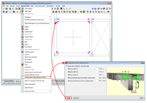
Users can assign them freely to any side or end of beams reaching columns. This way, slabs which have different geometric or mechanical properties at either side of the beam, or beams which only have the floor slab on one side can be contemplated.
To identify each of the sides and ends of the beam to which the data has been assigned for the capacity checks, the program displays small magenta triangles at these zones, which are displayed when the option Assign data for capacity check is selected. The triangles will be displayed in green at zones where the properties of the slab have not been assigned, in which case, the dimensions and steel areas of the slab will not intervene in the capacity checks for the concrete beams and columns.
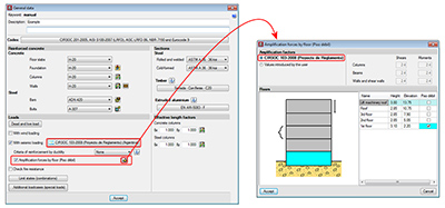
Seismic analysis with force amplification in open floors or with partitions that are less rigid than on other floors
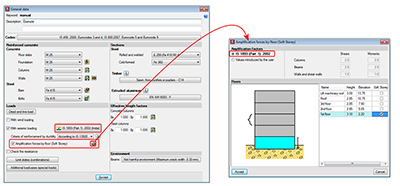
It is vitally important to consider the effect non-structural elements (façades and partitions) have on the behaviour of a building exposed to seismic action, especially when open floors are present or a floor contains partitions and façades that are less rigid than those on other floors.
There are design codes that oblige project designers to contemplate the absence or reduction of the stiffness of the partitions and façades on specific floors, by applying moment and shear amplification factors to columns, beams, walls and shear walls situated on floors with less stiffness than the rest when resisting the horizontal displacements caused by seismic action. Examples include IS 13920 (India) -Soft Storey- or Proyecto de Reglamento CIRSOC 103-2008 (Argentina). Logically, the tendency of standards and codes which do not contemplate these effects is to gradually take them into account.
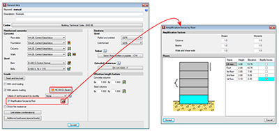
The 2013.l version of CYPECAD allows for moment and shear amplification factors to be applied to columns, beams, walls and shear walls situated on floors chosen by users, regardless of the selected code. To do so, the option Amplification forces by floor has been implemented n the General data dialogue box (Job > General data). Upon activating this option, a dialogue box appears with the same name. If the selected code contemplates the reduced floor stiffness effect due to weaker partitions, the program displays the corresponding moment and shear force amplification factors, which are then applied to the selected floors. Users also have the choice to indicate their own amplification factors. If the selected code does not contemplate these effects, the program allows users to introduce the values they wish for the floors they select.
This method to consider the effect the absence of partitions and façades on specific floors may have when exposed to seismic action, is an approximation to the real behaviour of the building.
CYPECAD contains a software tool that contemplates, in a more precise manner, the influence the distribution of the partitions and façades has on the building: the module Interaction of the structure with the construction elements.
Interaction of the structure with the construction elements
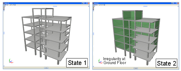
CYPECAD contains a software tool which allows for a dynamic analysis to be carried out on buildings with seismic loads acting upon them, which includes the effects of the non-structural construction elements used in the façades and partitions of the building, and considers various behavioural models of the building corresponding to different situations or states of these elements.
The façades and partitions of the building are considered as being “non-structural” elements, however, during an earthquake, they do provide stiffness to the structure, hence modifying the distribution and magnitude of the forces caused by the seismic action For example, when there is a non-uniform distribution between floors of the stiffness associated with the partitions, the horizontal forces have a greater impact on the columns belonging to the floors with less stiffness, producing shear forces of a high magnitude in the columns. If these have not been designed accordingly, the forces can cause a fragile fracture, endangering the stability of the building, even leading to its collapse.
This module has been developed by CYPE, with the collaboration of the Centro Internacional de Métodos Numéricos en Ingeniería (CIMNE) of the Universidad Politécnica de Cataluña (UPC), financed by the Centro para el Desarrollo Tecnológico Industrial (CDTI) and co-financed by the European Regional Development Fund (ERDF).
There are currently no software tools available on the market for the structural analysis of buildings which integrate the possibility of considering, in a simple manner, the façades and partitions, even though it has been proved that they directly affect the stability, stiffness and safety of the building during an earthquake. Since this CYPECAD module does integrate them, keeping the computation periods within an admissible period, their integration in the building projects will increase their quality and the safety of their occupants, allowing for unfortunate losses, both material and human, to be avoided after an earthquake.
More information can be found on the Interaction of the structure with the construction elements webpage.
Correction due to base shear for seismic design using dynamic analysis method
Certain seismic codes require for a minimum base shear to be met when the modal spectral dynamic method is applied to analyse seismic loading. The base shear check is implemented in CYPECAD for the following design codes:
- 2009 IBC (USA)
- 2011 PRBC (Puerto Rico)
- ASCE 7-05 (USA)
- CFE 2008 (Mexico)
- CHOC-04 (Honduras)
- COVENIN 1756-1:2001 (Venezuela)
- CSCR 2010 (Costa Rica)
- IS 1893 (Part 1): 2002 (India)
- NCh433.Of1996 Mod.2009 (Dºnº61 de 2011) (Chile)
- NEC -11 (Ecuador)
- Norma Técnica E.030 (Peru)
- NSE-10 (Guatemala)
- NSR-10 (Colombia)
- NTC-2004 (Mexico)
- R-001 2011 (Dominican Republic)
- REP-04 (Panama)
- RPA 99/v 2003 (Algeria)
- RPS 2011 (Morocco)
- RPS 2000 (Morocco)
- SANS 10160-4:2011 (South Africa)
The value of the total dynamic shear at the base (Vd), obtained having carried out the modal combination (CQC), for any of the analysis directions, cannot be less than a specific limiting value. This value is equal to a percentage (α) of the shear at the base of the structure which has been analysed with the static method (Vs). In other words, the following condition must be met: ![]()
If the minimum base shear condition is not met, the results of the dynamic analysis must be adjusted by the following factor: ![]()
The adjustment covers all the results of the dynamic analysis, including the displacements, distortions, forces at the floors, floor shears, base shear and forces in the elements.
Fundamental period of the structure with user values
Some seismic codes propose two methods to obtain the Fundamental period of the structure (used to calculate the base shear). The codes, which are implemented in CYPECAD which allow for this possibility are:
- CFE 2008 (Mexico)
Manual de Diseño de ObrasCiviles.DiseñoporSismo - COVENIN 1756-1:2001 (Venezuela)
Norma Venezolana COVENIN 1756-1:2001. Edificaciones sismorresistentes - NC 46:1999 (Cuba)
Construcciones sismoresistentes. Requisitos básicos para el diseño y construcción. - NEC 11 (Ecuador)
Norma Ecuatoriana de la Construcción. Capítulo 2.-Peligro sísmico y requisitos de diseño - Norma Técnica E.030 (Peru)
Norma Técnica E.030 DiseñoSismorresistente. - NSR-10 (Colombia)
Reglamento Colombiano de Construcción Sismo Resistente (2010) - NTC 2004 (Mexico)
Normas Técnicas Complementarias para Diseño por Sismo
With these codes, CYPECAD allows users to define the Fundamental period of the structure in two ways:
- Based on the code
- Specified by the user
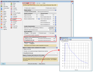
Either of the two options can be selected in the section: Estimation of the fundamental period of the structure within the Code for the calculation of seismic loading dialogue box (General data > Select “with seismic loading” from the “Loads” section > select one of the previously indicated codes).
The value of the fundamental period of a building must be obtained based on the properties of its seismic resistance system, in the direction being considered, in accordance with structural dynamic principles. Alternatively, most seismic codes allow for the fundamental period to be estimated:
- Using empirical formulas provided within their articles
- Using other methods, as long as these are adequately sustained analytically or experimentally
The estimated fundamental period is applied in the calculation of the static shear at the base of the structure (base shear) to adjust the dynamic results to minimum values prescribed in the code, if the dynamic method is applied and to generate the distribution of the equivalent static lateral forces, if the static method is applied.
The values indicated by the codes arelimits that can be used in the absence of more precise data. If users have values of the fundamental period which are more adjusted to their structure (calculated using their methods or using software such as CYPECAD, which calculates the fundamental period of the structure in each direction – the values can be consulted after the analysis in the “Justification of seismic action report”: File > Print job reports), they may specify them by selecting the Specified by the user option, located in the Code for the calculation of seismic loading dialogue box.
Seismic spectrum specified by users
For certain seismic codes in CYPECAD, users can specify a customised seismic spectrum different to that specified by the code.
A design spectrum must be defined for the seismic analysis of the structure. Each seismic code provides the criteria to be followed, within a specific territory, when considering seismic action in the project. Nevertheless, CYPECAD and CYPE 3D allow project designers to adopt, under their responsibility, different criteria to that established in the code. The programs allow the spectrum, in accordance with which the seismic analysis of the structure is to be carried out, to be defined in one of two ways. The design seismic spectrum can be:
- Calculated according to that specified in the seismic code to be applied
- Specified by users based on their own criteria
The seismic codes for which allow for a customised spectrum to be defined in CYPECAD and CYPE 3D are:
- NCh433.Of1996 Mod.2009 (Dºnº61. de 2011) (Chile)
Norma Chilena Oficial Diseño Sísmico de Edificios (Includes the modifications of decree nº 61 (V. y U.) of 2011). - NEC-SE-DS 2014 (Ecuador)
Norma Ecuatoriana de la Construcción. Peligro sísmico. Diseño sismo resistente. - NEC -11 (Ecuador)
Norma Ecuatoriana de la Construcción. Capítulo 2.- Peligro sísmico y requisitos de diseño. - Norma Técnica E.030 (Peru)
Norma Técnica E.030 Diseño Sismoresistente. - NSR - 10 (Colombia)
Reglamento Colombiano de Construcción Sismorresistente (2010).
This option will be implemented for more seismic codes in upcoming program versions.
 Using the Fire resistance check module, CYPECAD carries out a fire resistance check and designs the protective coating of the structural steel and concrete elements making up the job (beams, floor slabs, columns, shear walls and concrete walls, steel beams and columns, and steel bars within the integrated 3D structures).
The fire resistance check is not undertaken for concrete block walls or composite slabs in CYPECAD.
Using the Fire resistance check module, CYPECAD carries out a fire resistance check and designs the protective coating of the structural steel and concrete elements making up the job (beams, floor slabs, columns, shear walls and concrete walls, steel beams and columns, and steel bars within the integrated 3D structures).
The fire resistance check is not undertaken for concrete block walls or composite slabs in CYPECAD.
The fire resistance check for timber structural elements within the integrated 3D structures of CYPECAD is carried out by a different module: the Timber sections module (common to CYPE 3D and the Integrated 3D structures of CYPECAD).
More information can be found on the Fire resistance check webpage.
The joints modules designed by CYPE (Joints I. Welded. Warehouses with rolled and welded steel I sections, Joints II. Bolted. Warehouses with rolled and welded steel I sections, Joints III. Welded. Building frames with rolled and welded steel I sections, Joints IV. Bolted – Building frames with rolled and welded steel I sections) can be used in CYPECAD and CYPE 3D (including the Integrated 3D structures of CYPECAD)
The type of joints resolved using the Joints I and Joints II modules have a broader field of application in warehouses designed in CYPE 3D and the Integrated 3D structures of CYPECAD, whilst the types of joints designed using the Joints III and Joints IV modules is more applicable to building structures composed of frames designed in CYPECAD. Nonetheless, each joint that is designed by any of the indicated modules is resolved in the same way regardless of the program in which it is applied; as a matter of fact, the Joints I, Joints II, Joints III and Joints IV modules have common joint types.
More information on the properties of these modules can be found at the following links:
Joints I. Welded. Warehouses with rolled and welded steel I sections
- Implemented design codes for welded joints
- Types of implemented welded connections
- Design options
- Welded connection design
- Joint consultation
- Baseplates designed using the Joints I module
- Joints report
- Joints drawings
Joints II. Bolted. Warehouses with rolled and welded steel I sections
- Implemented design codes for bolted joints
- Types of implemented bolted connections
- Design options
- Prestressed and non-prestressed bolted connections
- Bolted connection design
- Joint consultation
- Bolted joints report
- Bolted joints drawings
Joints III. Welded – Building frames with rolled and welded steel I sections
- Implemented codes for the design of building welded connections
- Implemented type of building welded connections
- Design options
- Design of building welded connections
- Consulting welded joints
- Baseplates designed using the Joints III module
- Joints report
- Joints drawings
Joints IV. Bolted. Building frames with rolled and welded steel I sections
- Implemented design codes for bolted joints
- Types of implemented building bolted connections
- Design options
- Prestressed and non-prestressed bolted connections
- Bolted connection design
- Design of building welded connections
- Joint consultation
- Baseplates designed using the Joints IV module
- Joints report
- Bolted joints drawings
Joints V. Flat trusses with hollow structural sections
- Implemented design codes for the design of flat trusses with hollow structural sections
- Types of implemented connections for flat trusses with hollow structural sections
- Joint design of flat trusses with hollow structural sections
- Joint consultation of flat trusses with hollow structural sections
Analysis using multiprocessors
CYPECAD and CYPE 3D offer the use of multiprocessors during their analysis.
To acquire these tools, CYPECAD and CYPE 3D have two new common modules which allow for substantial periods of time to be saved during the analysis:
- Parallel analysis with two processors
- Parallel analysis with up to eight processors
Export to TEKLA® Structures and in CIS/2
Once the structure has been analysed, the columns, beams and construction details containing the designed joints (using the Joints I, Joint II and Joints III modules) of CYPECAD and its Integrated 3D structures can be exported to TEKLA Structures and in CIS/2 format. Concrete columns and beams are exported as generic bars, whilst steel columns and beams are exported as is done in CYPE 3D. More information can be found at Export to Tekla Structures and Export in CIS/2 format.
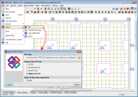
CYPECAD allows for all the structural elements which have been designed by the program (except corbels) to be exported to IFC format (Industry Foundation Classes). This way, the information that has been introduced and generated in CYPECAD can be read in CAD/BIM programs such as Allplan®, Archicad®, Revit® Architecture, etc.
To carry out the export, an option has been implemented in CYPECAD: Export to IFC format (File > Export).
Within the Export to IFC dialogue box (File > Export > IFC), users can choose amongst four IFC format variations for generating the export file:
- IFC 2x3
Generic format - IFC 4
Generic format - Archicad IFC 2x3
Specific format for Archicad - Revit IFC 2x3
Specific format for Revit Architecture - Allplan IFC 2x3
Specific format for Allplan
In the export process, CYPECAD assigns different colours to the materials of the structural elements which are exported (concrete, steel, aluminium, timber, masonry walls, generic bars from integrated 3D structures). When exporting to Archicad, textures are also generated for each material.
The export to IFC format includes the different types of joists (reinforced, prestressed, in situ, steel and open-web joists) present in joist floor slabs. These are also represented in the 3D views provided by CYPECAD.
CYPECAD also allows for IFC format files, which have been generated by CAD/BIM programs to be imported, thanks to the Automatic job introduction: DXF, DWG and CAD/BIM models module. More information on the import of IFC files in CYPECAD can be found in the Data entry (Structure geometry) section. For CYPECAD to export the job to IFC format, users are not required to have the "Automatic job introduction: DXF, DWG and CAD/BIM models" module.
There are many tools available to be able to check all the graphical results on screen.
After the analysis it is possible to visualise the deformed shape of the structure in 3D (with a colour scale), produced by the simple loadcases or by a combination of loadcases, including earthquake loading. It is also possible to observe an animation of the deformation process produced by the selected loadcase combination.
The displacements, forces, force combinations and steel areas of flat and solid slabs, slabs on grade and waffle slabs can be represented by contour maps (coloured diagrams in which each colour represents a value) and in contour line diagrams (curves that joint geometric points with the same value).
It also carries out a graphical consultation of envelopes, deflections, etc.
The reinforcement of all the elements can be modified with a subsequent check in foundation pads, pile caps, beams, columns and joist floor slabs.
With the beam reinforcement editor a complete visualisation of the frame is obtained where the user can graphically modify the results, add, delete, join and divide longitudinal bars and links as well as being able to modify their lengths and anchorage lengths.
It is possible to copy reinforcement amongst frames of the same or different floors and group frames in the same floor before and after the analysis.
The user may automatically equalise all the top reinforcement of joist floor slabs by length or bar size and length. This way, a more uniform reinforcement is obtained and, therefore, easier to place on site.
The program modifies waffle slab and flat slab reinforcement by means of view tables. The reinforcement can be copied from one floor to another, modify the geometry after the analysis and introduce reinforcement without analysing.
Editing of foundation pads, pile caps, base plates and strap and tie beams results to be a powerful tool allowing the check to be carried out of any geometry and reinforcement defined by the user. A report can be obtained of all the checks carried out on the foundations and view its compliance factor.
It is possible to equalise the geometry, type and reinforcement of pad foundations, pile caps, strap and tie beams and base plates.
Project drawings can be configured with different formats and paper sizes (standard or user defined). Additionally, these can be drawn by printer, plotter or exported to DXF or DWG format. It is possible to include the DXFs or DWGs that have been used to define the job in the floor drawings. All of the drawings can be integrated or only those layers that are deemed necessary, such as stairs.
In the floors of the job, a drawing editor is available, which allows multiple resources to be used: add dimensions, texts, building sections, construction details in DXF format, floor slab sections, modify text positions, etc. These modifications are saved with the project.
CYPECAD possesses a vast library of construction details: steel, concrete, mixed and inclined slab, available to incorporate to any of the drawings generated by the program. You may also acquire this library edited in two volumes that includes the details in DXF and DWG format.
- Consult more information on the Construction Detail Library. Inclined slabs.
- Consult more information on the Construction Detail Library of steel, concrete and mixed elements.
You may apply any scale, line thickness, font size, frame etc, This way you my completely personalise the drawing.
CYPECAD provides complete and clear drawings. You may obtain layout, floor plan, foundation, beam, column schedule, column and shear wall detail, foundation loads, wall elevation, stair, load, corbel, etc drawings. They optionally include take off and reinforcement detail tables. They can be configured so that our users obtain the drawing adjusted to each of their needs. CYPECAD has an incorporated editor that allows to move the texts whilst the drawing is being visualised on screen.

You may easily obtain reports of all the introduced data and of the results: job data report, combinations used in the analysis, foundation, corbel, envelopes, reinforcement and take-off of all the elements, job take-off, horizontal wind loads, participation coefficients (earthquake loading), second order effects, etc. All this is obtained on screen or printed out, but you may also create files in HTML, DXF, DWG, RTF, PDF, etc. format.
Detailed ultimate limit state check reports
CYPECAD, CYPE 3D and the Integrated 3D structures of CYPECAD generate detailed reports on the ultimate limit state checks of steel and aluminium sections.
These reports contain all the checks carried out by the program to design the structures and constitute an important document with which the user can:
- Verify the design of the sections
- Optimise the design of the sections
The level of detail of these reports also acts as a detailed guide so the user can know all the checks the section is submitted to.
Click here for more information on the Detailed ultimate limit state check reports.
Properties that distinguish CYPECAD
Automatic job introduction. Using CYPECAD’s Automatic job introduction: DXF, DWG and CAD/BIM models module, the user has two options which allow for a structure to be generated automatically: either by means of importing a file in IFC format, generated by the main CAD/BIM programs (Allplan, Archicad, Revit Architecture); or by using a file in DXF or DWG format.
Great analytical power. The inverse of the global stiffness matrix of the structures will be obtained in the least possible time thanks to the substructure condensation method and the system resolution of equations by frontal methods. With unlimited nodes and bars, in general practice.
Earthquake load analysis. A complete spectral mode analysis is undertaken resolving each mode as a loadcase carrying out the modal expansion and the modal combination to obtain the forces; all this without the need of having to produce equivalent earthquake static loads, which is the simplified method used by others.
Personalised analysis. A vast amount of analysis and reinforcement options are available to be able to take into account those aspects that are deemed most adequate. Additionally, for each structural element and each reinforcement position, personalised reinforcement tables may be defined.
Drawings can be personalised according to the user’s needs, as the program allows to configure all the drawing layers and elements and generate them via DXF, DWG, printer and plotter.
Versatility of the foundations. The foundation elements, namely pad foundations and pile caps can hold several supports, be they of the same type or a combination of columns, shear walls and wall spans.
In foundations, you may count with the aid of several strap beams in each direction and arrange for its centring effect to be produced at one end or at both.
Powerful reinforcement editor. For all design elements, their geometry and reinforcement can be edited and modified, with multiple tools to carry out the task.
Complete drawings. These are construction drawings, very complete, with the possibility to compose them and include construction details, DXF, DWG, borders, take-off tables, etc, and so, obtaining the most precise and detailed drawings to be able to carry out the job on site.
Export to TEKLA Structures and in CIS/2 format. The program has two additional modules, common to CYPECAD and CYPE 3D, which allow for the integrated 3D structures to be exported to TEKLA Structures and in CIS/2 format.
Over 1,100 details make up the extensive construction detail library on steel, concrete, mixed and inclined slab elements, available to include in the drawings generated by the program. You may also acquire this library edited in two volumes that includes the details in DXF and DWG format.
- Consult more information on the Construction Detail Library. Inclined slabs.
- Consult more information on the Construction Detail Library of steel, concrete and mixed elements.
Trustworthy analysis. CYPE, with over 45 million square metres of calculated structures, contribute to their programs their constant experience and that of over 46,000 users all over the world. This is the best guarantee we can offer.
Please consult our marketing department or your customary distributor of CYPE Ingenieros products for the different national and international codes that are available for this program and their corresponding prices.
And do no forget that our experts in our post sales service and technical support departments offer all the additional services you may need.
CYPECAD Modules
The following modules are those that can be acquired together with CYPECAD or CYPECAD LT:
CYPECAD versions
CYPECAD is available in its unlimited version and also in two limited versions called LT30 and LT50, which contain the same tools and module acquisition possibilities, but have the following conditions:
CYPECAD LT50:
- Fifty columns
- Four floor groups (Floor group: floors which are the same and consecutive)
- Total of five floors
- Walls: one hundred linear metres
CYPECAD LT30:
- Thirty columns
- Four floor groups (Floor group: floors which are the same and consecutive)
- Total of five floors
- Walls: one hundred linear metres
Integrated 3D structures of CYPECAD (also LT50 and LT30) is not technically a module. To define these 3D structures in CYPECAD, users must also have the required permits to use CYPE 3D in their user license and, optionally, modules which are exclusive to CYPE 3D.
- Steel columns
- Steel beams
- Joist floor slabs (generic concrete joists)
- Joist floor slabs (in-situ, precast and steel)
- Timber joist floor slabs
- Waffle slabs
- Flat slabs
- Punching shear verification (Also operates as an independent program)
- Composite slabs
- Hollow core slabs
- Post-tensioned concrete slabs for buildings
- Shear walls
- Reinforced concrete walls
- Plane stress walls
- Stairs
- Mat foundations and foundation beams
- Concrete block walls
- Interaction of the structure with the construction elements
- Automatic job introduction: DXF, DWG and CAD/BIM models
- Collective protection systems
Modules common to CYPECAD and CYPE 3D:
- Concrete columns
- Composite steel and concrete columns
- Concrete beams
- Timber sections
- Pile caps (includes strap and tie beams)
- Baseplates
- Footings (pad and strip) (includes strap and tie beams)
- Advanced design of surface foundations
- Fire resistance check
- Parallel analysis with two multiprocessors
- Parallel analysis with up to eight processors
- Joints I. Welded. Warehouses with rolled and welded steel I sections
- Joints II. Bolted. Warehouses with rolled and welded steel I sections
- Joints III. Welded. Building frames with rolled and welded steel I sections
- Joints IV. Bolted. Building frames with rolled and welded steel I sections
- Joints V. Flat trusses with hollow structural sections
- Export to Tekla
Tel. USA (+1) 202 569 8902 // UK (+44) 20 3608 1448 // Spain (+34) 965 922 550 - Fax (+34) 965 124 950