

Punching shear verification checks the Failure Limit State of concrete for punching shear in flat slabs, waffle slabs and mat foundations using two methods: Point tangential stress check and Check in accordance with the design standards.
The point tangential stress check also designs the required reinforcement. For waffle slabs, the reinforcement required in drop panels and lightweight zones (shear reinforcement in the ribs) is designed.
The punching shear check in accordance with design standards is also carried out by the “Punching shear verification” program, which has been designed exclusively to carry out this check  . Both CYPECAD and “Punching shear verification” carry out the check taking into account the reinforcement that has been included by users (reinforcement inclined at 45º or beam-type reinforcement).
- Punching shear verification in CYPECAD
- Tangential stress check
- Punching shear in accordance with code criteria
- Coexistence and complementation of the two methods
- Operation of the punching shear check
- Punching shear reinforcement quantities and drawings
- Implemented design codes
- Required user license permits
- CYPECAD modules
Punching shear verification in CYPECAD
CYPECAD checks the Failure Limit State of concrete for punching shear in flat slabs, waffle slabs and mat foundations using two methods: Point tangential stress check and check in accordance with the design standards.
A tangential stress verification is carried out on surfaces which are concentric to the perimeter of the support, between a distance of half the depth of the slab from the support and at intervals of 0.75 times the depth of the slab and drop panels of waffle slabs. The value of the tangential stress at the intersection points of the mesh with the punching shear perimeter is obtained using the shears at nearby nodes by means of linear interpolation. This stress is compared to the maximum punching shear tangential stress resistance (without taking into account the transverse reinforcement), which is calculated using the corresponding concrete code. The program designs the punching shear reinforcement, where it is required, and indicates the position of each vertical reinforcement bar in the plan view (on-screen and in drawings). In the lightweight zones of waffle slabs, the ribs are checked, and the minimum width of the nerve (which can vary when removable forms are used), is taken as the width of the section.
This approach, based on point tangential stress checks at the mentioned perimeters, is different to the punching shear failure check provided by different concrete codes.
In general, design codes use, as an alternative method, procedures which undertake a more precise evaluation of the tangential stress in surfaces which are concentric to the perimeter of the support, which is the case in the tangential stress check method of CYPECAD.
Punching shear in accordance with code criteria
In general, design codes use a nominal tangential stress within a critical surface area which is concentric to the loaded zone, and is calculated taking into account the reaction of the support and the moments it transfers to the slab. It is a simplification proposed by different codes; which also allow for the use of, as alternative method, procedures which provide a more precise evaluation of the tangential stress at surface areas which are concentric to the perimeter of the support, which is the case of the tangential stress check method referred to in the previous section.
The program carries out the punching shear verification in accordance with code criteria by following these steps:
- Critical punching shear area
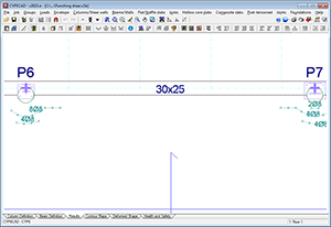
The program obtains and marks on-screen, the worst case critical punching shear area around the support, which is defined by its critical perimeter, and taking account the presence of openings or lightweight areas in the slab.
- Calculation of the worst case forces
The worst-case forces transmitted to the support by the slab along the punching shear surface are obtained.
- Stress calculation
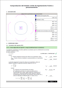
The program calculates the stress along the critical perimeter and compares the values with the stress withstood by the concrete.
- Punching shear reinforcement check
If users introduce punching shear reinforcement, the programs verifies whether the reinforcement provided meets all the requirements of the selected code.
The punching shear check in accordance with code criteria is carried out in the same way as in the “Punching shear verification” program, which can be accessed via the main CYPE program menu (Structures group).
Coexistence and complementation of the two methods
The final result obtained by both procedures may not coincide, even though both are valid.
The reinforcement calculated by CYPECAD, which depends on the point tangential stress, can be used as a reference to introduce punching shear reinforcement (reinforcement at 45º angles or beam-type reinforcement). Once introduced, CYPECAD automatically checks the reinforcement that has been provided by carrying out a punching shear verification in accordance with code criteria. If punching shear reinforcement is provided, the tangential stress reinforcement located within the surface area concentric to the support and limited by the critical punching shear perimeter, must be deleted to avoid it being duplicated in drawings and job quantities. To do so, a tool has been included in CYPECAD which allows for users to eliminate the tangential stress reinforcement .
Operation of the punching shear check
During the analysis of the job, CYPECAD checks the point tangential stress on flat slabs, waffle slabs, and mat foundations. If necessary, CYPECAD designs the transverse reinforcement (vertical bars with a spacing of 0.75 times the effective depth). The spacing of the vertical bars can be edited manually but the changes are not checked by the program. The reinforcement for flat and waffle slabs is taken from the same table, whereas a separate table is used for mat foundations.
This check and the design of the transverse reinforcement are carried out automatically by CYPECAD without users having to intervene. For this, users do not require any specific license permits; they must only have the permits which allow for the analysis of the floor slab types for which punching shear reinforcement check is to be carried out (flat slabs, waffle slabs or mat foundations).
More information on this check can be found in the “Tangential stress check” section of this webpage.
Check in accordance with code criteria
This check is the same check that is carried out by the “Punching shear verification” program, which operates independently of CYPECAD. For CYPECAD and “Punching shear verification” to be able to carry out the punching shear check in accordance with code criteria, the user license must contain the required permits to use the “Punching shear verification” program.
After the analysis and if users wish so, they can carry out the punching shear check and, if required, provide transverse punching shear reinforcement (bars inclined at 45º or beam-type reinforcement) which will substitute those that have been obtained using the tangential stress check and lie within the critical punching shear perimeter of the support that has been checked.
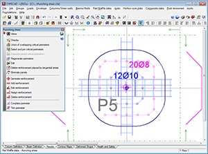
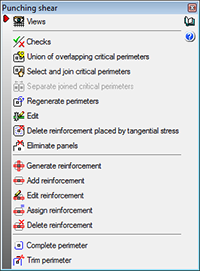
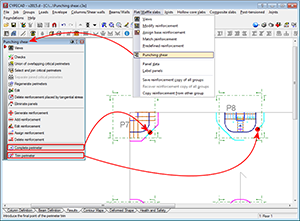
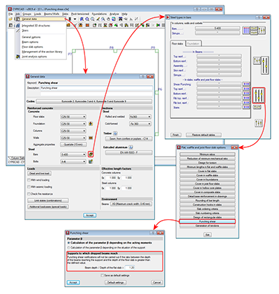
A series of options have been implemented in the “Punching shear” dialogue box (Results > Flat/Waffle slabs > Punching shear) to carry out the punching shear check and provide the required reinforcement:
- Views
Using this option, users can select the flat and waffle slab reinforcement to be seen on screen. - Checks
Allows users to view on screen, print or export (Text, HTML, PDF, RTF, DOCX) all the Failure Limit State checks for punching shear carried out by the program at the selected support. - Union of overlapping critical perimeters
This option creates the union of the intersecting critical perimeters of the supports. - Select and join critical perimeters
This option joins two or more critical perimeters. - Separate joined critical perimeters
This option separates critical perimeters which had previously been joined. - Regenerate perimeters
The program obtains the perimeters each time the job is analysed and when there significant data changes which may affect its composition. This is not carried out for other types of changes, such as when the width of a beam has been modified. Users can use this option, if deemed necessary, after having carried out this type of changes. This option eliminates any modifications carried out on the punching shear perimeters. - Edit
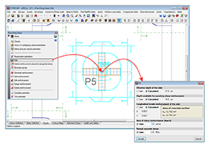
Having selected a support, this option opens a dialogue in which all the data that has been obtained automatically by CYPECAD is displayed, so it can be modified by users (effective depth of the slab, depth available for punching shear reinforcement, slab tensile reinforcement area).
An additional area “Asw” (cm2/m) of punching shear reinforcement and a normal concrete stress (kp/cm2) can also be added. For example, the section of transverse reinforcement of a beam (cm2/m) which lies within the zone contained by the critical punching shear perimeter is not taken into account automatically by the program (with regards to punching shear reinforcement) but, by consulting it using CYPECAD’s advanced beam editor (Results > Beams/Walls > Edit beams), it can be included in the “area of punching shear reinforcement (Asw/s)” field of the edit dialogue of the support selected using this option.
All the data defined here is used to generate the critical perimeter and carry out the punching shear resistance checks.
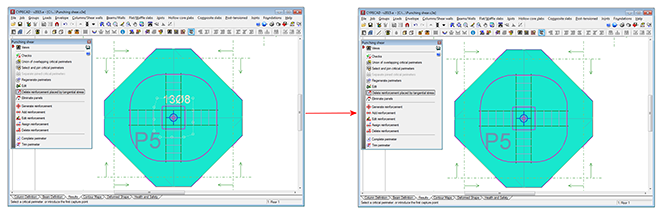
- Delete reinforcement placed by tangential stress
The reinforcement calculated by the program due to point tangential stress can be used as a reference to introduce punching shear reinforcement (bars inclined at 45º angles or beam-type reinforcement) and then carry out a punching shear verification in accordance with code criteria. In this case, the tangential stress reinforcement located within the critical punching shear perimeter should be deleted. This reinforcement can be deleted using this option and so avoid duplicating it on drawings and job quantities. - Eliminate panels
This option allows users to select panels for which punching shear checks are not to be carried out. - Generate reinforcement
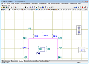
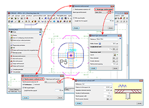
This option allows users to introduce two orthogonal reinforcement configurations at a support. - Add reinforcement
Users can add reinforcement in any direction and at any support. - Edit reinforcement
Allows users to edit punching shear reinforcement introduced at a support. - Assign reinforcement
Using this option, users can introduce reinforcement bars equal to other reinforcement that is already present. - Delete reinforcement
Deletes the selected reinforcement. - Complete perimeter
Allows users to draw the punching shear perimeter on zones at which it has been trimmed by the analysis or manually. - Trim perimeter
Allows users to trim the punching shear perimeter of a column.
To avoid the punching shear check from being carried out at a support next to dropped beams where the ratio of the depth of the beam to the depth of the floor slab is large, the program contains the option “Supports to which dropped beams reach” (Job > General data > By position button > Slab options > Punching shear) which does not allow the punching shear check to take place at a support if the ratio between the depth of the dropped beams adjacent to the support and the depth of the slab is greater than the value defined in this option. The default value for this ratio is 1.20.
Punching shear reinforcement quantities and drawings
The punching shear reinforcement quantities in waffle slabs, flat slabs and mat foundations, that have been calculated in accordance with the methods explained in this webpage (tangential stress or in accordance with code criteria) are listed in the takeoff report of the job (File > Print > Job report > Job takeoffs).
As to how it is presented in drawings (including its details table and quantities summary), the punching shear reinforcement is represented in different drawings:
- Reinforcement designed using the tangential stress check
The punching shear reinforcement is included by default in the layout drawing of each floor (File > Print > Job drawings > Add drawing icon > select “Floor plans” > select “Layout” plan). Even though the other floor drawings do not contain the punching shear reinforcement by default, they can be configured to include it. - Reinforcement provided in accordance with code criteria
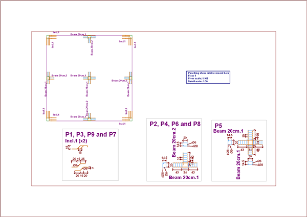
A specific drawing is available to represent the punching shear reinforcement provided by users. This is the “Punching shear reinforcement” drawing (File > Print > Job drawings > Add drawing icon > Select “Punching shear reinforcement” drawing). This drawing displays an on-plan view of the punching shear reinforcement provided by users, its details, take-off table and quantities summary.
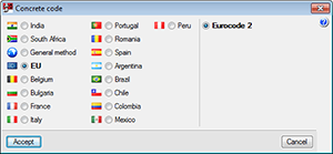
The punching shear check using the tangential stress method and the design of the required reinforcement is available for all the concrete codes that can be selected in CYPECAD.
The punching shear check in accordance with code criteria and therefore, the possibility to include reinforcement inclined at 45ª or beam-type reinforcement, are available for the majority of concrete codes implemented in CYPECAD. They are the same codes users can select in the “Punching shear verification” program. These codes are listed in the “Implemented codes” section of the program’s webpage.
For CYPECAD to carry out the point tangential stress check in flat slabs, waffle slabs and mat foundations, and for it to design the corresponding reinforcement (vertical bars), users do not require any specific license permits; they must only have the permits which allow for the floor slab types for which punching shear reinforcement check is to be carried out to be analysed (flat slabs, waffle slabs or mat foundations).
For CYPECAD and “Punching shear verification” to be able to carry out the punching shear check in accordance with code criteria, the user license must include the permits to use the “Punching shear verification” program. For CYPECAD, as well as this permit, users must have the required user license permits to analyse the type of floor slab for which the punching shear check is to be carried out (waffle slabs, flat slabs or mat foundations).
CYPECAD versions
CYPECAD is available in its unlimited version and also in two limited versions called LT30 and LT50, which contain the same tools and module acquisition possibilities, but have the following conditions:
CYPECAD LT50:
- Fifty columns
- Four floor groups (Floor group: floors which are the same and consecutive)
- Total of five floors
- Walls: one hundred linear metres
CYPECAD LT30:
- Thirty columns
- Four floor groups (Floor group: floors which are the same and consecutive)
- Total of five floors
- Walls: one hundred linear metres
Integrated 3D structures of CYPECAD (also LT50 and LT30) is not technically a module. To define these 3D structures in CYPECAD, users must also have the required permits to use CYPE 3D in their user license and, optionally, modules which are exclusive to CYPE 3D.
CYPECAD Modules
The following modules are those that can be acquired together with CYPECAD or CYPECAD LT:
- Steel columns
- Steel beams
- Joist floor slabs (generic concrete joists)
- Joist floor slabs (in-situ, precast and steel)
- Timber joist floor slabs
- Waffle slabs
- Flat slabs
- Punching shear verification (Also operates as an independent program)
- Composite slabs
- Hollow core slabs
- Post-tensioned concrete slabs for buildings
- Shear walls
- Reinforced concrete walls
- Plane stress walls
- Stairs
- Mat foundations and foundation beams
- Concrete block walls
- Interaction of the structure with the construction elements
- Automatic job introduction: DXF, DWG and CAD/BIM models
- Collective protection systems
Modules common to CYPECAD and CYPE 3D:
- Concrete columns
- Composite steel and concrete columns
- Concrete beams
- Timber sections
- Pile caps (includes strap and tie beams)
- Baseplates
- Footings (pad and strip) (includes strap and tie beams)
- Advanced design of surface foundations
- Fire resistance check
- Parallel analysis with two multiprocessors
- Parallel analysis with up to eight processors
- Joints I. Welded. Warehouses with rolled and welded steel I sections
- Joints II. Bolted. Warehouses with rolled and welded steel I sections
- Joints III. Welded. Building frames with rolled and welded steel I sections
- Joints IV. Bolted. Building frames with rolled and welded steel I sections
- Joints V. Flat trusses with hollow structural sections
- Export to Tekla
Tel. USA (+1) 202 569 8902 // UK (+44) 20 3608 1448 // Spain (+34) 965 922 550 - Fax (+34) 965 124 950