

CYPECAD contains a software tool that allows users to carry out a dynamic analysis of buildings exposed to seismic loads, which includes the effect of the non-structural construction elements used in the façades and partitions of a building. The program considers several behavioural models of the building corresponding to the different situations or states of these elements.
The program also generates complete justification reports of the analysis method used, and verifies that the seismic design criteria are met in accordance with the national and international codes.
This option is included in the CYPECAD module: “Interaction of the structure with the construction elements”.
This module is the result of the R+D+I project “Methodology for the dynamic analysis of buildings exposed to seismic action, incorporating the effect of the non-structural elements and the development of a software tool with BIM model” developed by CYPE, with the collaboration of the Centro Internacional de Métodos Numéricos en Ingeniería (CIMNE) of the University Politécnica de Cataluña (UPC), financed by the Centro Tecnológico Industrial (CDTI) and co-financed by the European Regional Development Fund (ERDF).
- Effect of the non-structural elements against horizontal loads
- A unique tool on the market
- Data introduction
- Considerations taken into account by the program
- Considerations taken into account by the program from the version 2014.g
- Considerations taken into account by the program in its first versions (2014.a ‑ 2014.f)
- Example of the analysis carried out by the program
- Required user licence permits
Effect of the non-structural elements against horizontal loads
The façades and partitions of the building are considered as being “non-structural” elements, however, during an earthquake, they do provide stiffness to the structure, hence modifying the distribution and magnitude of the forces caused by the seismic action For example, when there is a non-uniform distribution between floors of the stiffness associated with the partitions, the horizontal forces have a greater impact on the columns belonging to the floors with less stiffness, producing shear forces of a high magnitude in the columns. If these have not been designed accordingly, the forces can cause a fragile fracture, endangering the stability of the building, even leading to its collapse.
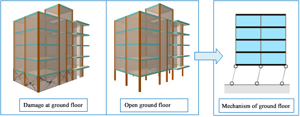
The non-uniform stiffness distribution between floors causes there to be greater forces acting on the columns of the less rigid floors, giving rise to fragile fractures if the elements have not been designed accordingly.
This is the case of buildings, whose ground floor is destined to be used as retail precincts, and are, generally, irregularly stiff, causing them to be weaker at that floor. The difference in stiffness is due to the height of that floor usually being higher than that of the other floors, and that, due to the use of the floor, it is an open floor. Even if the floor below were to have a similar stiffness to that of those above, during the first instants of the earthquake, the partitions of the lower parts of the building fracture, causing an abrupt change in the stiffness, and therefore, an irregularity similar to that described previously. Hence, the stiffness provided by the different non-structural elements can change during the seismic action, due to the cracks and fractures which appear successively.
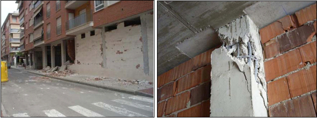
Damaged ground floor façades and columns during the Lorca earthquake (2011)
A unique tool on the market
There are currently no software tools on the market for the structural design of buildings which integrate the possibility to consider, in a simple manner, the effect of the façades and partitions, including how the stiffness varies due to their presence, which may change during an earthquake, due to them fracturing or cracking.
Using current means, a project engineer with a high level of structural analysis experience and knowledge could include the non-structural elements in a design model, by taking into account the non-linear behaviour of the materials. This would, however, require, amongst other things, a great time investment transforming the architectonic data into numerical data, as well as having to carry out a considerable analysis of the results so to obtain the required construction drawings for the execution of the job. Another fact to take into account is that as the elements are not structural elements, there is generally not a lot of data available regarding the behaviour of the materials, which is essential for the numerical model.
CYPECAD’s module: Interaction of the structure with the construction elements, allows users to verify the behaviour of the structure in different situations, by automatically generating design models which consider how the stiffness of the non-structural elements varies. The module verifies the behaviour of the structure without partitions or façades, with all of them, considers intermediate states (see Considerations taken into account by the program in its first version), and designs each resistant element for the worst case situation, this way guaranteeing the correct response of the structure for all the behaviour loadcases during an earthquake.
Data introduction
CYPECAD’s module: Interaction of the structure with the construction elements, generates and considers, not only the loads associated with these elements, but also their stiffness and how it may vary during the earthquake, based on the mechanical and elastic properties of the partitions and façades that have been introduced.
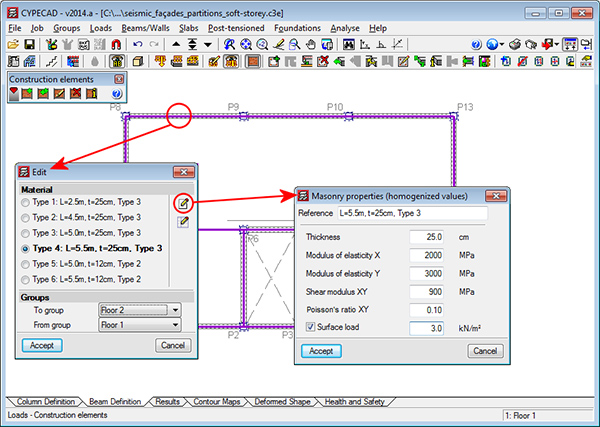
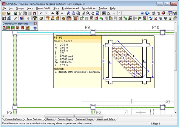
To introduce these non-structural elements, the option, Construction elements has been implemented in the Loads menu in the Beam Definition tab. The Construction elements option opens a window which allows users to introduce (a single element or polygon composed of them), edit, delete and obtain information on the façades and partitions. When a construction element is introduced, a dialogue box opens where users can define the geometric and mechanical properties of the façades and partitions which are to be introduced in the job: Thickness of the masonry, Modulus of elasticity X of the homogenised masonry, Modulus of elasticity Y of the homogenised masonry, Shear modulus XY of the homogenised masonry, Poisson’s ratio XY of the homogenised masonry and Surface load (this last property is optional and can be activated if the program is to automatically take into account the self-weight of the element).
The stiffness of the non-structural elements introduced is considered in the analysis by applying the method proposed by the “Centro Internacional de Métodos Numéricos en Ingeniería” (CIMNE) of the “Universidad Politécnica de Cataluña” (UPC). It must be pointed out that this stiffness is only developed if the non-construction element is laterally confined between columns, shear walls or reinforced concrete walls. Otherwise, the program generates the corresponding line load, but does not assign any stiffness to it.
Therefore, users must bear in mind that if a façade or partition is interrupted by an opening (window, door…), it must be introduced including these interruptions (or not introduce it but include its self-weight manually), so the program can assign it its corresponding stiffness.
Additionally, so the stiffness the construction elements could provide, is taken into account, the option, Construction elements (Job > General data > Loads) must have the Interaction with the structure value assigned to it.
Considerations taken into account by the program
As has been indicated, the stiffness analysis of the non-structural elements that have been introduced is carried out by applying the method proposed by the “Centro Internacional de Métodos Numéricos en Ingeniería” (CIMNE) of the “Universidad Politécnica de Cataluña” (UPC). When construction elements have been introduced in CYPECAD, so their interaction with the structure can be considered (using the option within the “Loads” menu, for elements that are “laterally confined”, and if the value “Interaction with the structure” has been assigned within the “General data” menu – see the section on Data introduction), the program allows for the behaviour of the building to be verified for different situations, automatically generating, analysis models that take into account the stiffness variation of the non-structural elements. It verifies the behaviour of the structure without any façades or partitions, with all the façades and partitions and considering intermediate states, hence designing each resistant element for the worst case situation and, this way, guaranteeing the correct response of the structure for all the possible behaviour loadcases during an earthquake.
The program contemplates the stiffness each construction element (laterally confined) provides to the building, whilst the forces that arise during the earthquake, do not cause it to fail. As of that moment, the construction element no longer provides any stiffness and the distribution of the forces in the building changes. The program takes into account the different behaviour states during the failure process of the façades and partitions, and will design the resistant elements for the worst case situation.
Considerations taken into account by the program from the 2014.g version
Using the Interaction of the structure with the construction elements module, users can carry out a dynamic analysis of buildings subjected to seismic action, which includes the effect the non-structural elements used in the partitions and façade have on the building. Furthermore several behaviour models of the building are considered corresponding to different situations or states of these elements.
This module was implemented in the 2014.a version and considered two extreme states: State 1, corresponding to the behaviour of the structure without the effect of any construction elements, and State 2 considering the effect of all the laterally confined construction elements by including their stiffness in the dynamic model and assuming they are completely effective, i.e., that they have not cracked or fractured.
As of the 2014.g version, the program allows for intermediate states to be defined between States 1 and 2. These are generated automatically depending on a fracture criterion which relates the damage suffered by an element with the relative displacement of its ends. These are intermediate states, in which each laterally confined element provides a percentage of its stiffness depending on the level of damage it has reached.
These intermediate states are generated automatically based on the model in which all the construction elements are considered to be effective (State 2). A modal spectral analysis of the model produces a relative displacement between the ends of each construction element which, upon applying the fracture criterion, is interpreted as being a specific level of damage. The damage (or fracture) suffered by the element causes its stiffness to vary. The new stiffness obtained for each construction element is included in the new dynamic model which is used for the next modal analysis. New relative displacements are obtained and each element reaches a new damage level, with their change in stiffness, and so the next model is generated. This process is repeated successively for each seismic loadcase that is considered.
This iterative process stops when the damage level stabilises between two states (which occurs when the difference between the level of damage of the last analysed state and the previous state is less than 5% for each element) or when the maximum number of iterations established by users is reached. This will be the Final state.
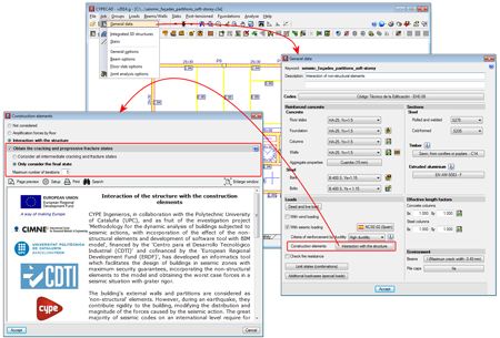
The automatic generation of these intermediate states can substantially multiply the number of seismic loadcases that are considered, hence CYPECAD allows users to configure this iterative process in the Construction elements dialogue box (Job > General data > Loads section > Construction elements option). Users have to activate the Interaction with the structure option (located at the top). Once activated, another option appears: Obtain the cracking and progressive fracture states. If this option is deactivated, CYPECAD will only generate states 1 and 2, as was done in the 2014.a version. If the option: Obtain the cracking and progressive fracture states is activated, the following options appear:
- Consider all intermediate cracking and fracture states
By choosing this option, CYPECAD considers all the states (State 1, State 2 and Intermediate states) that have been generated when designing the structure. By activating this option, the time required to analyse the job could substantially increase, depending on when the Final state is reached.
- Only consider the final state
All the states are analysed but CYPECAD only considers State 1, State 2 and the Final state when designing the structure.
Below these options, users can limit the Maximum number of iterations. This number will determine which is the final state, if this state is not reached before the maximum number of iterations has been undertaken
As the structure is analysed several times, if all the cracked intermediate states are considered as of the first analysis, the design process of the structure could be quite long. Therefore, for the first analyses, it is best if Only consider the final state is activated. Once any problems involving the dimensions of the structural elements have been solved (and the follow-up analysis has concluded), users should then consider activating Consider all intermediate cracking and fractured states and maybe increasing the Maximum number of iterations.
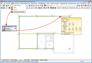
To help users decide, as of the 2014.g version, a new option has been implemented: Damage level (Results tab >Loads > Construction elements). Using this option, users can consult the relative displacement and associated damage, per generated state and seismic loadcase of each construction element. This information allows users to know if the iterative process that has been configured is adequate or must be changed:
- If, for any seismic loadcase, the difference between the last state of a construction element and its previous state is greater than 5%, the maximum number of iterations should be increased. Otherwise the number is adequate.
- If the option “Only consider the final state” has been activated and the difference in damage between the final state and the other intermediate states (X1, X2… or Y1, Y2…) is small, users do not have to activate the “Consider all intermediate cracking and fracture states” option.
This check should be carried out for all the construction elements of each floor.
Help explanations are included within the mentioned dialogue box, which describe the implications of these options.
The approximation carried out by the 2014.a version (which can also be carried out as of the 2014.g version, by not activating the Obtain the cracking and progressive fracture states option) is acceptable for buildings with an open-floor ground floor which, generally are irregularly stiff, causing them to be weaker at that floor (buildings whose ground floor is destined to be used as retail precincts, garages…).
Nonetheless, and as it is not possible to generalise for all these cases, it is recommended the 2014.g version be used and that an analysis be carried out taking into account the intermediate cracking or fracture states. Please bear in mind that users who have any 2014 version can update to the latest version for free. Therefore, we recommend these users, especially those whose licence contains the “Interaction of the structure with the construction elements” module, to update to the latest 2014 version. This way, the automatic generation of intermediate states option will be available to them. ![]()
Please recall that the building partitions and façades are considered as being “non-structural” elements, however during an earthquake, they do provide stiffness to the structure, hence modifying the distribution and magnitude of the forces caused by the seismic action. If these structural elements have not been designed accordingly for this distribution, the forces can cause a fragile fracture, endangering the stability of the building, even leading to its collapse. The Interaction of the structure with the construction elements module allows users to consider the effect the non-structural elements have on the structure during an earthquake and as of the 2014.g version, the program automatically generates the intermediate cracked and fractured states.
Considerations taken into account by the program in its first versions (2014.a ‑ 2014.f)
The first versions of the “Interaction of the structure with the construction elements” module (2014.a ‑ 2014.f) do not yet contemplate the intermediate states. In these versions, the program generates two analysis models: without any partitions or façades and with all the partitions and façades, introduced as indicated earlier on ![]() . This approximation is acceptable for buildings with open ground floors which, are usually, irregularly stiff, making them weaker at that floor (buildings whose ground floor is for retail use, garages...). The difference in stiffness is due to the height of the ground floor being greater than that of the floors above it and also, because of its use, is an open floor. Even if the stiffness of the ground floor were to be similar to that of the other floors, during the first instances of an earthquake, the first partitions to fracture are those in the lower parts of the building, which cause abrupt changes in the stiffness, and hence an irregularity similar to that mentioned earlier.
. This approximation is acceptable for buildings with open ground floors which, are usually, irregularly stiff, making them weaker at that floor (buildings whose ground floor is for retail use, garages...). The difference in stiffness is due to the height of the ground floor being greater than that of the floors above it and also, because of its use, is an open floor. Even if the stiffness of the ground floor were to be similar to that of the other floors, during the first instances of an earthquake, the first partitions to fracture are those in the lower parts of the building, which cause abrupt changes in the stiffness, and hence an irregularity similar to that mentioned earlier.
To create this situation in the program (v.2014.a ‑ v.2014.f), simply introduce a building with the same uniform distribution, at each floor, of partitions and façades, except the ground floor, which is left open with no construction elements. The results obtained by the program for this situation are analysed in the example below ![]() .
.
If users wish to create other situations or behaviour states of the building with the 2014.a, 2014b, 2014c, 2014d, 2014e or 2014 f versions, different jobs must be created. For example, if users wish to study the case of a building in which the ground floor and an intermediate floor are less stiff than the other floors, two identical structures can be analysed, one with construction elements on all floors except the ground floor and another with construction elements on all floors except the ground and intermediate floors. Users will have to compare the two jobs to assign the worst case design to each structural element. If the stiffness of the intermediate floor were to be substantially less than that of the ground floor, a third structure could be analysed in which the construction elements are introduced at all floors except the intermediate floor.
As of the 2014.g version, the program allows for intermediate states to be defined between States 1 and 2. These are generated automatically depending on a fracture criterion which relates the damage suffered by an element with the relative displacement of its ends. These are intermediate states, in which each laterally confined element provides a percentage of its stiffness depending on the level of damage it has reached ![]() .
.
Nonetheless, and as it is not possible to generalise for all these cases, it is recommended the 2014.g version be used and that an analysis be carried out taking into account the intermediate cracking or fracture states. Please bear in mind that users who have any 2014 version can update to the latest version for free. Therefore, we recommend these users, especially those whose licence contains the “Interaction of the structure with the construction elements” module, to update to the latest 2014 version. This way, the automatic generation of intermediate states option will be available to them. ![]()
Example of the analysis carried out by the program
The behaviour of a building during an earthquake is going to be analysed, taking into account the stiffness provided by its partitions and façades using the “Interaction of the structure with the construction elements” module of CYPECAD.
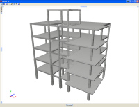
The structure consists of a reinforced concrete building with 6 floors (5 + lift machinery room), made up of frames with spans ranging between 4,5 and 5,6 m and with 15 cm thick flat slabs. The frames are composed of columns which start at foundation level and measure 45x45 cm, and are reduced to 30x30 cm at the higher floors; the beams are 30x30 cm dropped beams. The height of each floor is 3 m.
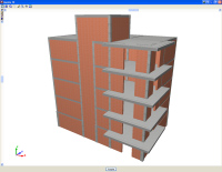
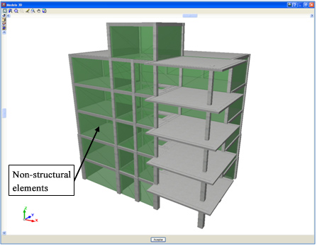
In addition to the structurally resistant system (columns-beams-slabs), partitions and façades are also introduced (non-structural elements). These consist of 25 cm and 10 cm thick masonry walls.
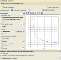
A modal spectral analysis shall be considered for the seismic action, applying the NCSE-02 Spanish code. The location, type of soil, properties of the structure and other parameters shall be selected; the program then generates the corresponding spectrum with which the analysis is carried out.
Analysis and results of the example
The aim of this example is to demonstrate how important it is to consider how the stiffness differs along the height of the building, as it causes greater forces to arise in the resistant elements of the floors with less stiffness.
As has been indicated previously, it is those buildings whose ground floor is for retail use that, generally, have a stiffness irregularity, making them weaker at that floor. The difference in stiffness is due to their height usually being greater than that of the floor above and, that due to their use, is a much more open floor. Even if the stiffness of the ground floor were to be similar to that of the floors above it, during the first instants of an earthquake, the partitions of the lower zones of the building are the first to fail, which causes abrupt changes in the stiffness and, therefore, an irregularity similar to that described previously. Therefore, the stiffness provided by the various non-structural elements can change during an earthquake, due to the cracks and fissures that appear successively.
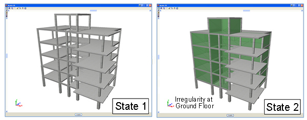
A uniform distribution of partitions and façades has been introduced along the building’s height, except for the ground floor. The program automatically analyses two models or states: the model in which only the structural elements are considered and the model that includes the structural elements and their interaction with the non-structural elements, contemplating the stiffness of the latter elements in the stiffness analysis.
The dynamic modal spectral analysis provides two mode groups corresponding to the states that have been considered. For each state, the modal responses (forces, displacements, distortions, etc.) are combined using the CQC method to obtain the response for each seismic loadcase (Earthquake X and Earthquake Y) and for each state, in such a way that the following dynamic loadcases are considered:
- Earthquake X (state 1)
- Earthquake X (state 2)
- Earthquake Y (state 1)
- Earthquake Y (state 2)
Both states are considered in the combinations of the seismic action with the other static actions, designing each structural element for the worst case situation it is exposed to.
Displayed below are some sections of the “Justification of seismic action” report provided by the program. The two calculated mode sets are displayed for the two states of the structure that have been considered with their participation coefficients, percentage of displaced mass in each direction and associated spectral acceleration. The information contained in the tables on the design spectrums used in the analysis is then displayed on a graph, and the period intervals that have been studied for each state are represented.
If the results are observed, it can be seen that the periods of state 2, in which the effect of the non-structural elements is considered, are smaller than those obtained for state 1, i.e. state 2 takes into account a model with greater stiffness than that in state 1.
Depending on the stiffness of the models, the intervals and, therefore, their associated accelerations will vary. Additionally, the vibration modes are different for each state, affecting the resistant elements in a different manner. This explains why a state can be the worst case state for a specific resistant element, but not for another. Hence, the new implemented tool will analyse the elements considering both states.
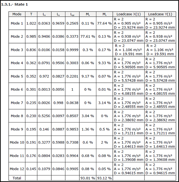
Participation coefficients for state 1
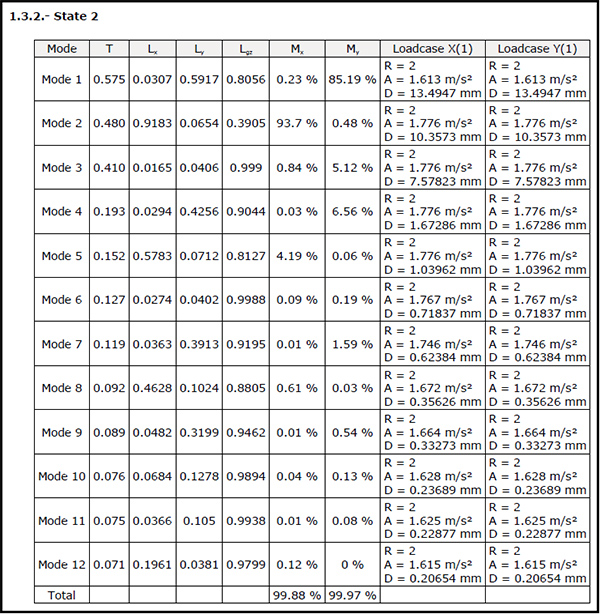
Participation coefficients for state 2
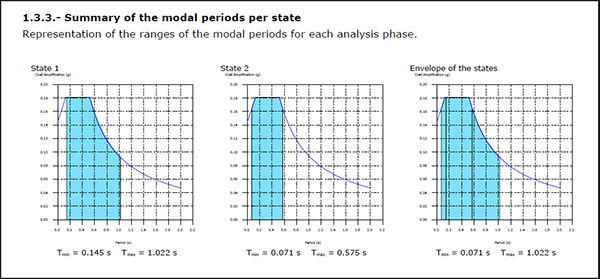
Graphical representation of the period intervals for each state.
Superposition of the states (For Earthquake X loadcase)
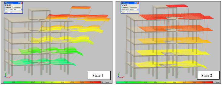
Deformed shape associated to the mode that displaces the most mass in the X direction for each state.
The forces for each mode and state, for each seismic loadcase are displayed in the “Forces and reinforcement of columns, shear walls and walls” report.
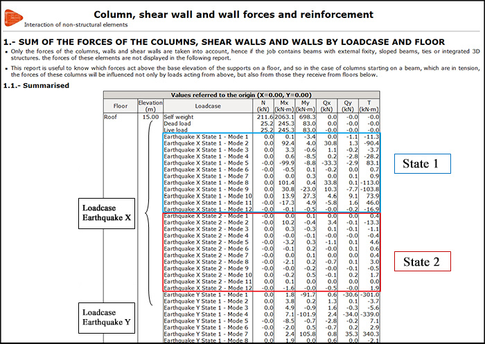
“Forces and reinforcement of columns, shear walls and walls” report.
The element check reports display that the static load and dynamic load combinations of both the states have been taken into account in the analysis. This way, different seismic behaviour loadcases are considered; the worst case being taken to design the element. For example, below is the check of “Failure due to shear (seismic combinations)” for a column span between floor 4 and roof, and a span between foundation and floor 1. It can be seen that the worst case situation for the first example is for state 1, and for the second example is for state 2.
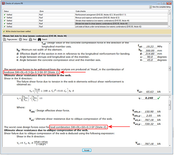
Check on “Failure due to shear (seismic combinations) for column P9.
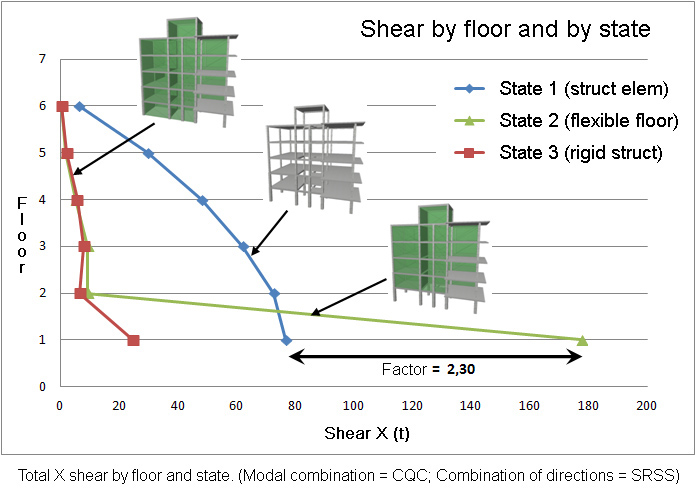
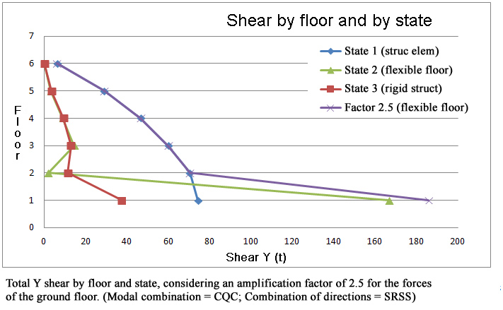
To conclude, a comparison is carried out of the total shear per floor, in each analysis direction, produced by the seismic loadcase for each stiffness state that is considered. By considering the effect or interaction of the non-structural elements, the irregularity of the structure can be automatically taken into account in the analysis. When there is a non-uniform distribution between floors of the stiffness associated with the partitions, the horizontal forces have a greater impact on the columns belonging to the floors with less stiffness, producing shear forces of a high magnitude in the columns. If these have not been designed accordingly, the forces can cause a fragile fracture, endangering the stability of the building, even leading to its collapse.
The new tool allows users to place the partitions and façades on the various floors, taking into account their stiffness If they have not been distributed in the same way on each floor, a stiffness irregularity will automatically be generated, which is considered directly in the analysis. In this example, it can be seen with the ground floor, which is an open floor and therefore has less stiffness. The following graph displays the total shear per floor produced by the seismic loadcase for each stiffness state that has been considered. It can be seen that, for the case in which the stiffness irregularity is considered, the forces at the ground floor are much greater (approximately twice as large) than those obtained if this irregularity is not considered. Hence the analysis results generated before applying this new method (only state 1 was provided) provided smaller forces that those which could arise.
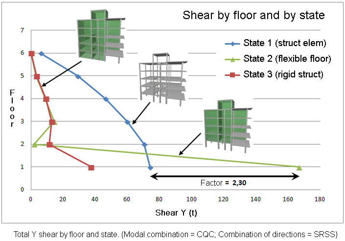
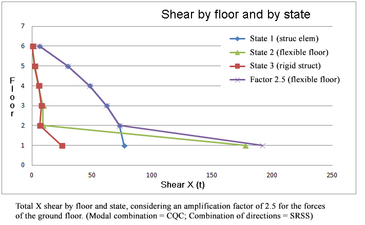
This unfavourable effect was not taken into account in the analysis until now and many design codes offer the possibility to simulate it by amplifying the forces of a floor that is considered as a soft-storey, by a specific factor. The shears and moments resulting from the analysis in which only the structural elements have been considered, are amplified by a factor that varies depending on the seismic design code that has been considered. The improvement provided by this new tool is that the analysis itself tells us directly which floor is soft, without the designer having to establish it before the analysis. Additionally, the force amplification factor is no longer left to the designer’s judgement, nor is it applied in a deterministic manner based on a design code; the analysis itself provides us with the value of the amplification factor. As can be seen in the example, the factor obtained from the analysis is 2.3 for Earthquake X and 2.25 for Earthquake Y. These values are within the range of values provided by design codes for which shear forces are to be amplified due to “soft-storey” effects, which range between 1.5 and 2.5. Therefore, the analysis itself, upon including the stiffness irregularity, provides greater forces in the least rigid floor, without the need of having to consider the effect indirectly by amplifying specific forces later on.
Required user licence permits
To be able to use the “Interaction of the structure with the construction elements” module of CYPECAD, users are required to have the required permits on their user licence, as well as the permits corresponding to the design codes and structural elements which are to be used.
CYPECAD versions
CYPECAD is available in its unlimited version and also in two limited versions called LT30 and LT50, which contain the same tools and module acquisition possibilities, but have the following conditions:
CYPECAD LT50:
- Fifty columns
- Four floor groups (Floor group: floors which are the same and consecutive)
- Total of five floors
- Walls: one hundred linear metres
CYPECAD LT30:
- Thirty columns
- Four floor groups (Floor group: floors which are the same and consecutive)
- Total of five floors
- Walls: one hundred linear metres
Integrated 3D structures of CYPECAD (also LT50 and LT30) is not technically a module. To define these 3D structures in CYPECAD, users must also have the required permits to use CYPE 3D in their user license and, optionally, modules which are exclusive to CYPE 3D.
CYPECAD Modules
- Steel columns
- Steel beams
- Joist floor slabs (generic concrete joists)
- Joist floor slabs (in-situ, precast and steel)
- Timber joist floor slabs
- Waffle slabs
- Flat slabs
- Punching shear verification (Also operates as an independent program)
- Composite slabs
- Hollow core slabs
- Post-tensioned concrete slabs for buildings
- Shear walls
- Reinforced concrete walls
- Plane stress walls
- Stairs
- Mat foundations and foundation beams
- Concrete block walls
- Interaction of the structure with the construction elements
- Automatic job introduction: DXF, DWG and CAD/BIM models
- Collective protection systems
Modules common to CYPECAD and CYPE 3D:
- Concrete columns
- Composite steel and concrete columns
- Concrete beams
- Timber sections
- Pile caps (includes strap and tie beams)
- Baseplates
- Footings (pad and strip) (includes strap and tie beams)
- Advanced design of surface foundations
- Fire resistance check
- Parallel analysis with two multiprocessors
- Parallel analysis with up to eight processors
- Joints I. Welded. Warehouses with rolled and welded steel I sections
- Joints II. Bolted. Warehouses with rolled and welded steel I sections
- Joints III. Welded. Building frames with rolled and welded steel I sections
- Joints IV. Bolted. Building frames with rolled and welded steel I sections
- Joints V. Flat trusses with hollow structural sections
- Export to Tekla
Tel. USA (+1) 202 569 8902 // UK (+44) 20 3608 1448 // Spain (+34) 965 922 550 - Fax (+34) 965 124 950