
import of IFC files generated by CAD/BIM programs and of DXF and DWG files
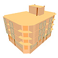
CYPECAD was brought about to carry out the analysis and design of reinforced concrete and steel structures, subject to horizontal and vertical forces, for houses, buildings and civil work projects.
Its use guarantees maximum analysis reliability and the best drawing design, including the following elements:
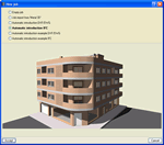
Automatic introduction of jobs in CYPECAD
The module: Automatic job introduction: DXF, DWG and CAD/BIM models of CYPECAD has two options available which have been conceived to automatically generate the structure:
- Import of IFC files from CAD/BIM programs
- Interpretation of DXF and DWG files
In both cases the structure is generated automatically after the use of an assistant which prompts the user to confirm or complete data contained in these files.
Import of IFC files from CAD/BIM programs
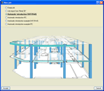
Using the Automatic introduction IFC option, the Automatic job introduction: DXF, DWG and CAD/BIM models allows for the import to CYPECAD of IFC files generated by the main CAD/BIM programs (Allplan®, Archicad®, Revit® Architecture). By means of an assistant, the user confirms and completes the information obtained from the IFC file, after which, the following elements of the structure are generated:
 When introducing a structure you may use any of the three methods mentioned above.
- Floor distributions
- Loads on floors
- Columns
- External perimeter and internal openings perimeter beams
- Partition and façade wall line loads
- Drawing templates of each floor
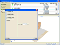
The Automatic introduction IFC assistant contains a series of dialogue boxes where data is displayed or is to be filled in, which will generate the job.
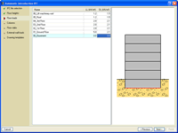
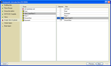
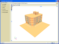 IFC file selection
In this dialogue box, the user indicates where the IFC file is located, which will then be used by the program to import the data displayed in the following steps of the automatic introduction.
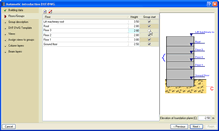
 Floor heights
In this section the heights of all the floors contained in the selected IFC file are defined. CYPECAD proposes the heights and names of the floors contained in the IFC file. The user may confirm or modify this data. The type of foundation the job is to have is also indicated here: Fixed (with external fixity) or Floating (without external fixity) and the elevation of the foundation plane.
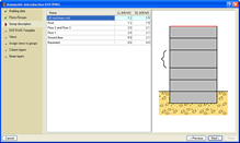
 Floor loads
Here, the user indicates the dead and live loads of the floors contained in the selected IFC file.
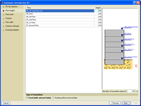
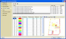
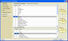
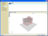 Columns
In this dialogue box, a list of column type elements (IFCCOLUMN entity) contained in the IFC file is displayed. The user activates those to be imported to generate the structural column of the job.
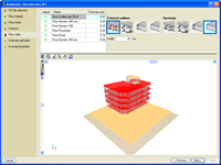 Floor slabs
In this dialogue box, a list of floor slab and roof elements (IFCSLAB and IFCROOF entities) contained in the IFC file is displayed. The user activates the slab and roof types for which CYPECAD is to define their external perimeters and internal opening perimeters. The beam defining these perimeters must also be defined.
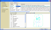
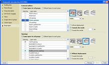
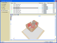 External wall loads
Here, a list of all the wall and partition type elements (IFCWALL and IFCWALLSTANDARCASE) contained in the IFC file is displayed. The user activates the walls and partitions for which their loads are to be obtained to place them automatically as line loads in the job in CYPECAD.
CYPECAD obtains the value of the line loads based on the dimensions of the selected walls and partitions; and the surface loads chosen by the user from a dialogue box in which the composition and surface weight of several types of walls are indicated. It is possible to choose a generic type of wall whereby the user assigns the value of the surface weight.
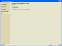 Drawing templates
In this dialogue box, the user can activate the automatic creation of drawing templates to add them to the job in CYPECAD containing the elements selected here: columns, floor slabs, external walls and auxiliary elements. A template is created per floor.
The default setting of the program is to not have the auxiliary elements activated. The user may activate it but this will probably imply that a drawing template containing a lot of information will be generated, and therefore will be of a large size.
It is possible that the IFC file may contain an element that, within the CAD/BIM program, was originally defined as a column, slab or roof element (IFCCOLUMN, IFCSLAB or IFCROOF) and is not really a structural element and therefore, the user does not wish for it to be imported in CYPECAD. A similar case occurs with wall loads; these may not be required as their loads have already been included in the dead load of the floors.
For this reason, the automatic introduction IFC assistant allows the user to activate the elements to be imported in the Columns, Floor slabs and External wall loads sections.
Within the 3D views of the structure which appear in the Columns, Floor slabs and External wall loads sections, the elements CYPECAD reads from the IFC file are displayed in different colours. These correspond to IFCCOLUMN, IFCSLAB and IFCROOF, and IFCWALL and IFCWALLSTANDARCASE entities respectively.
The colours are present to differentiate between those which have been selected from the list and the remaining elements of the current dialogue box which have been activated to be imported, those which have not been activated and those belonging to other sections:
- Element selected from the list of the current dialogue box
Intense red and opaque if the element has been marked to be imported by CYPECAD.
Light red and transparent if it has not been marked. - Elements
not selected from the list of the current dialogue box.
Orange and opaque if they have been marked to be imported.
Light grey and transparent if they have not been marked.
Elements from other dialogue boxes of the assistant. - Light grey and transparent if they have been activated to
be imported.
Are not drawn if they have not been activated.
Interpretation of DXF and DWG files
The Automatic job introduction: DXF, DWG and CAD/BIM models of CYPECAD also interprets DXF and DWG files to automatically generate the structure of the job (floor distribution, general loads, columns, external perimeter and internal openings perimeter beams) thanks to the indications given by the user via the assistant.
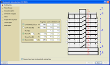
The user defines the floor composition of the structure (basements, ground floor, floors, roof, lift machinery roof…). Excluding the ground floor and roof, all the other floors are optional. Their respective heights, live and dead loads are also indicated.
The DXF or DWG files corresponding to the structure are then selected and the layers representing the columns, external outline and opening perimeters are defined.
The types of beams defining the external outline of the structure and internal outline of the openings can be selected as well as optionally assigning a displacement to the beam with respect to the original outline. This option may result to be very useful as the outline drawn on the DXF or DWG file may represent the edge position of the façade and not the structural edge.
Using all this information, the program automatically generated the geometry of the structure (columns and beams), and even deduces the fixed points of the columns if their dimensions are different on each floor of the DXF or DWG files that have been provided. It is also possible to indicate a layer defining the position of the fixed points of the columns so these are not automatically elected by the program.
Using the geometry of the beams and columns, the user may carry out any manual modifications of the generated structure, introduce slabs and complete its definition.
If the user has purchased the Automatic job introduction: DXF, DWG and CAD/BIM models module, when introducing beams manually, an additional option: Beam introduction using Snap mode. This option may be used during the manual introduction of beams and assigns any type of beam to a DXF or DWG file polygon or line at any floor. The polygon may be composed of straight or curved lines, and may be open or closed. This way it is not necessary to have to introduce the polygon geometry beam by beam.
CYPECAD also allows for the job to be exported to IFC format. To do so, users are not required to have the "Automatic job introduction: DXF, DWG and CAD/BIM models" module. More information can be found in the Export to IFC format section in the CYPECAD page.
CYPECAD versions
CYPECAD is available in its unlimited version and also in two limited versions called LT30 and LT50, which contain the same tools and module acquisition possibilities, but have the following conditions:
CYPECAD LT50:
- Fifty columns
- Four floor groups (Floor group: floors which are the same and consecutive)
- Total of five floors
- Walls: one hundred linear metres
CYPECAD LT30:
- Thirty columns
- Four floor groups (Floor group: floors which are the same and consecutive)
- Total of five floors
- Walls: one hundred linear metres
Integrated 3D structures of CYPECAD (also LT50 and LT30) is not technically a module. To define these 3D structures in CYPECAD, users must also have the required permits to use CYPE 3D in their user license and, optionally, modules which are exclusive to CYPE 3D.
CYPECAD Modules
The following modules are those that can be acquired together with CYPECAD or CYPECAD LT:
- Steel columns
- Steel beams
- Joist floor slabs (generic concrete joists)
- Joist floor slabs (in-situ, precast and steel)
- Timber joist floor slabs
- Waffle slabs
- Flat slabs
- Punching shear verification (Also operates as an independent program)
- Composite slabs
- Hollow core slabs
- Post-tensioned concrete slabs for buildings
- Shear walls
- Reinforced concrete walls
- Plane stress walls
- Stairs
- Mat foundations and foundation beams
- Concrete block walls
- Interaction of the structure with the construction elements
- Automatic job introduction: DXF, DWG and CAD/BIM models
- Collective protection systems
Modules common to CYPECAD and CYPE 3D:
- Concrete columns
- Composite steel and concrete columns
- Concrete beams
- Timber sections
- Pile caps (includes strap and tie beams)
- Baseplates
- Footings (pad and strip) (includes strap and tie beams)
- Advanced design of surface foundations
- Fire resistance check
- Parallel analysis with two multiprocessors
- Parallel analysis with up to eight processors
- Joints I. Welded. Warehouses with rolled and welded steel I sections
- Joints II. Bolted. Warehouses with rolled and welded steel I sections
- Joints III. Welded. Building frames with rolled and welded steel I sections
- Joints IV. Bolted. Building frames with rolled and welded steel I sections
- Joints V. Flat trusses with hollow structural sections
- Export to Tekla
Tel. USA (+1) 202 569 8902 // UK (+44) 20 3608 1448 // Spain (+34) 965 922 550 - Fax (+34) 965 124 950