
General properties of the In-situ, precast and steel joists module of CYPECAD
Using the In-situ, precast and steel joists module, the following types of joist floor slabs can be analysed and designed:
- Reinforced precast joist floor slabs
- Precast prestressed joist floor slabs
- In-situ joist floor slabs
- Steel joist floor slabs
- Open-web joist floor slabs
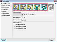
Defining in-situ, precast and steel joist floor slabs
Reinforced and prestressed precast joist floor slabs

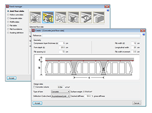
Users can select reinforced precast joist floor slabs from the panel manager. The program then requires the following data to be defined:
- Compression layer thickness
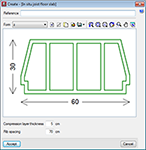
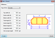
- Geometry of the form
- Concrete volume
The program calculates the approximate volume of concrete per unit surface area by taking into account the geometric parameters that have been introduced. Users can, however, introduce their own values. - Type of form
Users can choose amongst concrete, ceramic or polystyrene forms, for which the program automatically calculates the surface weight based on the form dimensions that have been introduced. Alternatively, users can select generic forms and introduce the surface weight manually. - Deflection code check
The program carries out a deflection check based on the approximate analysis of the cracked stiffness of the joists. This approximation is done differently depending on whether the joists are reinforced or prestressed.
For reinforced joists, the program calculates the required steel area to withstand the positive moment of the joist, and this is the value used to calculate the approximate cracked stiffness.
For prestressed joists, users have to introduce the cracked stiffness as a percentage of the gross stiffness. Having consulted manufacturer tables, this percentage usually oscillates between 50% and 100%. The gross stiffness of the joists is calculated based on the geometrical parameters and assuming ribs of constant width with slanted sides at the level of the compression layer.
The files or authorisations for these floor slabs have been provided by several manufacturers and are included in the program. If users wish to introduce their own data, they can do so using the Joist floor slab editor.
CYPE’s Joist floor slab editor is a free software application which can be downloaded from our website and is also included in the CYPE program installation USB. The editor generates a file with FVA format which can be imported directly to CYPECAD.
More information on this program (download, installation, data introduction, joist floor slab files for all CYPECAD users...) can be found on the Precast, reinforced and pre-stressed joist floor slab editor webpage.
In-situ joist floor slabs

These are floor slabs with joists built completely on site. They are reinforced in similar way as are concrete beams. They can be assigned a bottom base reinforcement using the option: Slabs > Assign base reinforcement. Users have to define the following floor slab elements:
- Compression layer thickness
- Rib spacing
- Form material
- Form geometry
- Unit weight of the form
Steel joist floor slabs
These are rolled T or I-section steel joist floor slabs and are designed as simply supported elements. Users have to define the following floor slab elements:
- Compression layer thickness
- Rib spacing
- Steel section series for the joist
- Form material
- Form geometry
- Unit weight of the form
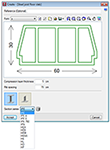
Open-web joist floor slabs
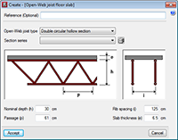
These are floor slabs composed of trussed joists which are designed as simply supported elements. Users have to select the following elements to define the floor slab:
- Type of open-web joist:
- Double circular hollow section
- Double rectangular hollow section
- Quadruple rectangular hollow section
- Double angles
- Quadruple angles
The top and bottom chords of the truss are composed of one or two equal sections, depending on the selected type, whilst the diagonals are composed of a single section and all are of the same section.
- Total depth of the truss
- Truss spacing
- Joist spacing
- Thickness of the top slab
Library of in-situ, precast and steel joists
The files of the reinforced precast and pre-stressed joist floor slabs generated by users can be saved. The forms that are defined for use in in-situ joist floor slabs and steel joist floor slabs can also be included in a form library. The steel sections used as steel joists and open-web joists are selected in the sections library of the program and can be broadened by users.
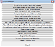
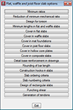
Design options
The program has a series of design options available with default values which users can configure (minimum top reinforcement lengths, minimum moments to be covered with reinforcement, deflection limits, rounding-off of bar lengths...).
Results obtained
The following results are displayed on-screen and on-plan for in-situ, precast and steel joist floor slabs:
- Precast joist floor slabs
- Bending moments per metre width, with applied safety coefficient
- Shear forces per metre width at supported ends, with applied safety coefficient
- The type of lattice for reinforced precast joists
- Top reinforcement
- In-situ joist floor slabs
- Bending moments per metre width, with applied safety coefficient
- Shear forces per metre width at supported ends, with applied safety coefficient
- Diameter and length of bottom reinforcement
- Diameter and spacing of shear reinforcement
- Top reinforcement
- Steel joist floor slabs
- Bending moments per metre width, with applied safety coefficient
- Shear forces per metre width at supported ends, with applied safety coefficient
- Section of the designed steel joist
- Top reinforcement
- Open-web joist floor slabs
- Bending moments per metre width, with applied safety coefficient
- Shear forces per metre width at supported ends, with applied safety coefficient
- Designed lattice reinforcement
- Top reinforcement
The program has tools available to match design results so that uniform results can be obtained, to provide comprehensible drawings.
CYPECAD versions
CYPECAD is available in its unlimited version and also in two limited versions called LT30 and LT50, which contain the same tools and module acquisition possibilities, but have the following conditions:
CYPECAD LT50:
- Fifty columns
- Four floor groups (Floor group: floors which are the same and consecutive)
- Total of five floors
- Walls: one hundred linear metres
CYPECAD LT30:
- Thirty columns
- Four floor groups (Floor group: floors which are the same and consecutive)
- Total of five floors
- Walls: one hundred linear metres
Integrated 3D structures of CYPECAD (also LT50 and LT30) is not technically a module. To define these 3D structures in CYPECAD, users must also have the required permits to use CYPE 3D in their user license and, optionally, modules which are exclusive to CYPE 3D.
CYPECAD Modules
The following modules are those that can be acquired together with CYPECAD or CYPECAD LT:
- Steel columns
- Steel beams
- Joist floor slabs (generic concrete joists)
- Joist floor slabs (in-situ, precast and steel)
- Timber joist floor slabs
- Waffle slabs
- Flat slabs
- Punching shear verification (Also operates as an independent program)
- Composite slabs
- Hollow core slabs
- Post-tensioned concrete slabs for buildings
- Shear walls
- Reinforced concrete walls
- Plane stress walls
- Stairs
- Mat foundations and foundation beams
- Concrete block walls
- Interaction of the structure with the construction elements
- Automatic job introduction: DXF, DWG and CAD/BIM models
- Collective protection systems
Modules common to CYPECAD and CYPE 3D:
- Concrete columns
- Composite steel and concrete columns
- Concrete beams
- Timber sections
- Pile caps (includes strap and tie beams)
- Baseplates
- Footings (pad and strip) (includes strap and tie beams)
- Advanced design of surface foundations
- Fire resistance check
- Parallel analysis with two multiprocessors
- Parallel analysis with up to eight processors
- Joints I. Welded. Warehouses with rolled and welded steel I sections
- Joints II. Bolted. Warehouses with rolled and welded steel I sections
- Joints III. Welded. Building frames with rolled and welded steel I sections
- Joints IV. Bolted. Building frames with rolled and welded steel I sections
- Joints V. Flat trusses with hollow structural sections
- Export to Tekla
Tel. USA (+1) 202 569 8902 // UK (+44) 20 3608 1448 // Spain (+34) 965 922 550 - Fax (+34) 965 124 950