

Using the “Concrete columns” module, CYPECAD and CYPE 3D design rectangular and circular reinforced concrete columns.
Data introduction
Using the “Concrete columns” module, CYPECAD and CYPE 3D check rectangular and circular reinforced concrete columns in accordance with the selected code.
CYPECAD and CYPE 3D also design composite steel and concrete columns using the Composite steel and concrete columns module, and steel columns (only CYPECAD requires the Steel columns module).
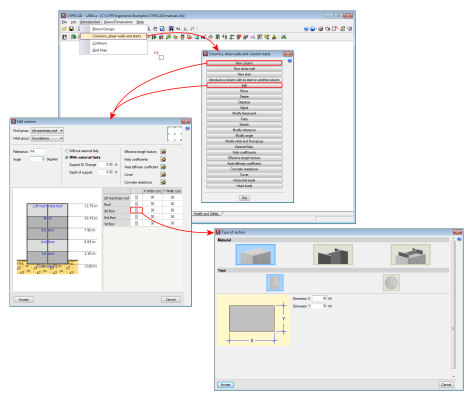
CYPECAD allows users to define, for each column that is introduced, specific values for the following parameters during its introduction (whose values are defined in the general data of the job or in the analysis options):
- Effective length factors
- Fixity coefficients at the top and bottom of each column span
- Axial stiffness coefficients
- Cover
- Concrete resistance
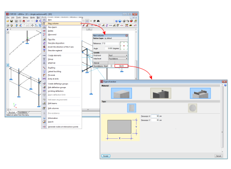
In CYPE 3D, these properties are defined using different options in the Bar menu.
In CYPECAD, when introducing the data, the fixed point of the columns can be defined (at corners or faces) for when the section size of a column varies from one floor to another. In CYPE 3D, the fixed point is defined using the “Describe disposition” option in the “Bar” menu. Columns introduced in CYPECAD and in CYPE 3D must be vertical. CYPECAD does not allow for them to be introduced any other way, however in CYPE 3D, users could define a bar, as being a column-type structural element, whose local X-axis is at an angle with respect to the global Z-axis. In these cases, CYPE 3D marks the bar as containing an error (if the “Show/Hide incidents” option in the “Analysis” menu has been activated) with the following message: “The element must be vertical, with its local X-axis in the ascending direction”. The program does not allow for the structure to be analysed (and also displays this problem if the analysis is launched regardless of whether the “Show/Hide incidents” option has been activated or not) until the direction of the local X-axis of the bar does not coincide with that of the global Z-axis.
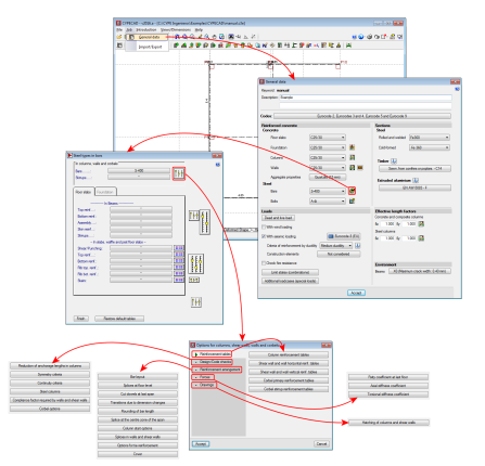
Design options
Users can also configure a series of options which affect how the columns are designed. For example: reinforcement symmetry criteria, reinforcement bar continuity criteria (sections, bars or diameters at faces and corners), fixity coefficient at the last floor, etc.
In CYPECAD, these option are centralised in the columns, shear walls, walls and corbels options dialogue (“Job” menu in the “Column Definition” tab or “Beam Definition” tab > “General data” > “Reinforcement bar steel” button > “Column options” button. See image).
In CYPE 3D, the column options can be found in the Columns dialogue box (Job > General data > Columns button in the Options section. See image).
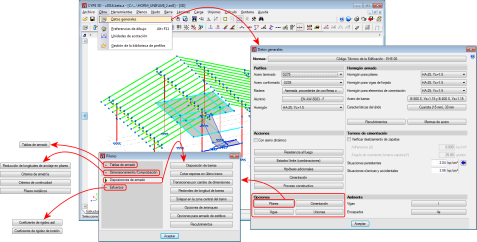
Automatic generation of reinforcement tables
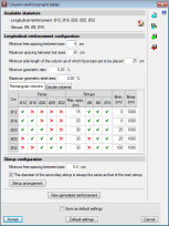
CYPECAD and CYPE 3D automatically generate reinforcement tables for concrete columns, for the design codes which use the Advanced Column Editor.
This feature is of great use to users who wish to use their own reinforcement tables, since they do not have to perform the laborious task of creating their own tables and there is the added guarantee that the reinforcement table that is generated is coherent and responds to their expectations. Furthermore, users, which in previous versions did not create their own tables due to the complexity of the task, can now customise them easily.
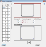
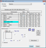
For design codes that do not use the Advance column editor, reinforcement tables are not generated automatically. Included in CYPECAD are longitudinal and transverse (stirrups) reinforcement tables for each section type. If seismic loads are applied on the structure, special reinforcement tables exist, which users must choose depending on the ductility of the structure and the basic acceleration. All these reinforcement tables can be configured by users. New tables can be created based on existing tables and users can choose to use the original or modified tables as they wish.
Please remember that CYPE 3D does not design reinforced concrete columns if the selected concrete and seismic codes are not available for use with the Advanced column editor. More information on the Advanced and Classic column editors can be found in the next section.
Results analysis
CYPECAD has two column editors: the Classic column editor and Advanced column editor (this last editor has more features) . Both editors are currently in use and whether one or the other is used depends on the concrete and seismic codes that are selected to design the structure (Job > General data).
CYPE 3D also includes the Advanced column editor (available since the 2016.a version) and uses it to edit bars defined as "Column" structural type elements (concrete, steel or concrete) when the selected concrete and seismic codes are available for use with the editor. More information on the different types of structural elements that can be assigned to bars in CYPE 3D (Generic, Tie, Column and Beam), can be found in the "Bar menu. Introduction of bars as structural elements" section in the New features of the 2016.a version webpage.
The Advanced beam editor is available for specific concrete and seismic codes (for both CYPECAD and CYPE 3D). Usually, concrete codes which are no longer in force are those which cannot be used with the editor.
More information on the codes which can be used with the editor can be found on the Advanced column editor webpage in the "Codes available for use with the Advanced column editor" section.
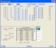
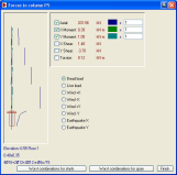
Using the editor of versions earlier than the 2012.a version, column force graphs can be consulted by loadcase in a dialogue box, which also displays the numerical results as the cursor is moved along the graphs.
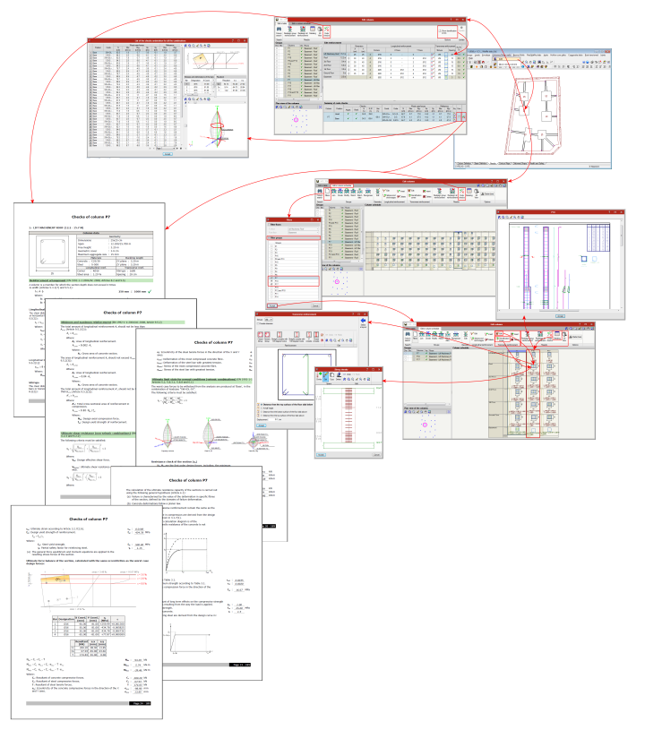
The program marks the column sections that fail in red at each floor in question. Users can view a dialogue box in which the program provides information on the problem that has been detected. The worst case forces used to design the column can be viewed, and its section and reinforcement can be modified. If changes are carried out, using the forces obtained from the last analysis, users can redesign the column in the same dialogue box. It is, however, recommended that the job be reanalysed if the column sections have been modified.
CYPECAD contains tools to match column dimensions and reinforcements after the analysis. This allows users to obtain more feasible construction plans. Sometimes, due to small changes in the structure, the job must be reanalysed. So not to lose any reinforcement modifications, the program allows users to block the reinforcement. The program will emit a warning if any of the columns with blocked reinforcement fails any checks after the structure has been reanalysed.
The program provides reports indicating forces, reinforcement, displacements, quantities, etc.
CYPECAD and CYPE 3D contain an advanced column editor (for concrete, steel and composite columns), which allows users to:
- Display all the information related to its design (only checks for composite columns), and generated ultimate limit state (U.L.S.) check reports.
- Organise groups in the column schedule, filter its view, modify reinforcement or steel sections used, and all this on a column schedule view and not on a plan view. It also has a miniature view of the columns on plan, so users can select to which type of column a specific column belongs to in the view.
- Check all the modifications that have been carried out.
- Redesign all the columns (except composite steel and concrete columns, for which only their check is currently available).
Detailed information on this powerful tool available for use with CYPECAD and CYPE 3D can be found on the "Advanced column editor" webpage. ![]()
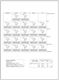
Drawings
Using the "Edit drawing " dialogue box (File > Drawings) in CYPECAD and CYPE 3D, users can configure the drawings for the job, amongst which are the "Column schedule" and "Detailing of columns" drawings. These drawings include all the modifications users may have carried out using either column editor (classic or advanced).
Required user license permits
For CYPECAD or CYPE 3D to design reinforced concrete columns, the user license must contain the permits to use either program, and the "Concrete columns" module (module for use with CYPECAD and CYPE 3D).
CYPECAD and CYPE 3D modules
CYPE 3D modules:
CYPECAD modules:
- Steel columns
- Steel beams
- Joist floor slabs (generic concrete joists)
- Joist floor slabs (in-situ, precast and steel)
- Timber joist floor slabs
- Waffle slabs
- Flat slabs
- Punching shear verification (Also operates as an independent program)
- Composite slabs
- Hollow core slabs
- Post-tensioned concrete slabs for buildings
- Shear walls
- Reinforced concrete walls
- Plane stress walls
- Stairs
- Mat foundations and foundation beams
- Concrete block walls
- Interaction of the structure with the construction elements
- Automatic job introduction: DXF, DWG and CAD/BIM models
- Collective protection systems
Modules common to CYPECAD and CYPE 3D:
- Concrete columns
- Composite steel and concrete columns
- Concrete beams
- Timber sections
- Pile caps (includes strap and tie beams)
- Baseplates
- Footings (pad and strip) (includes strap and tie beams)
- Advanced design of surface foundations
- Fire resistance check
- Parallel analysis with two multiprocessors
- Parallel analysis with up to eight processors
- Joints I. Welded. Warehouses with rolled and welded steel I sections
- Joints II. Bolted. Warehouses with rolled and welded steel I sections
- Joints III. Welded. Building frames with rolled and welded steel I sections
- Joints IV. Bolted. Building frames with rolled and welded steel I sections
- Joints V. Flat trusses with hollow structural sections
- Export to Tekla
Tel. USA (+1) 202 569 8902 // UK (+44) 20 3608 1448 // Spain (+34) 965 922 550 - Fax (+34) 965 124 950